Chimney cap link

a chimney and cap technology, applied in the field of frame mounted slidable pipe link assembly, can solve the problems of not opening or providing any access inside, and the need to address the need still exists in the ar

Inactive Publication Date: 2016-02-11
THOMPSON PETER ROMAIN
View PDF4 Cites 1 Cited by
  • Summary
  • Abstract
  • Description
  • Claims
  • Application Information

AI Technical Summary

Benefits of technology

[0010]In one embodiment, the frame mounted slidable pipe link assembly further includes two metal flexible leaf snap in locks (8). Measuring four inches by one inch in width with one sixteenth of an inch in thickness. Attached to the lower area of the frame (25), they rise up in a slope leading under the protruding bottom of the sliding sleeve (1) when it is locked in place. Bent outward at the top ends one inch, then upward one inch, in which providing small handles to grip, and pull out or push and snap in against the pipe wall.

Problems solved by technology

However, it does not open or provide any access inside the flue itself, which presents again another major difference.
Therefore, a heretofore unaddressed need still exists in the art to address the aforementioned deficiencies and inadequacies.

Method used


Image

  • Chimney cap link
  • Chimney cap link
  • Chimney cap link

Examples


Embodiment Construction

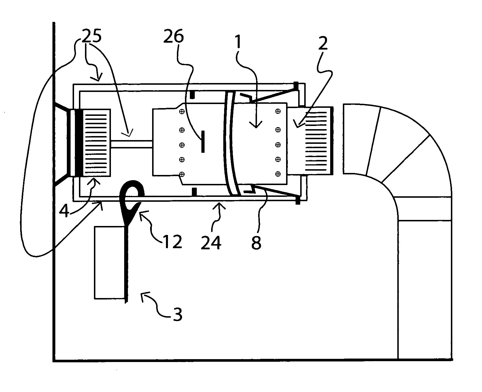
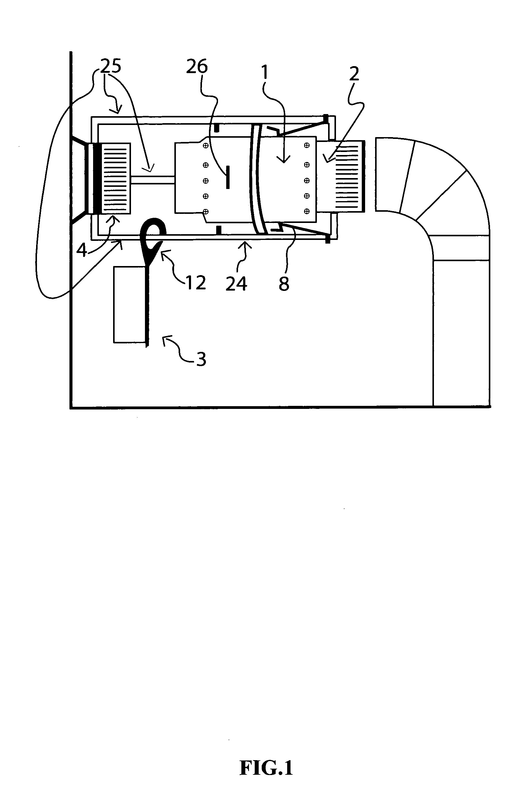
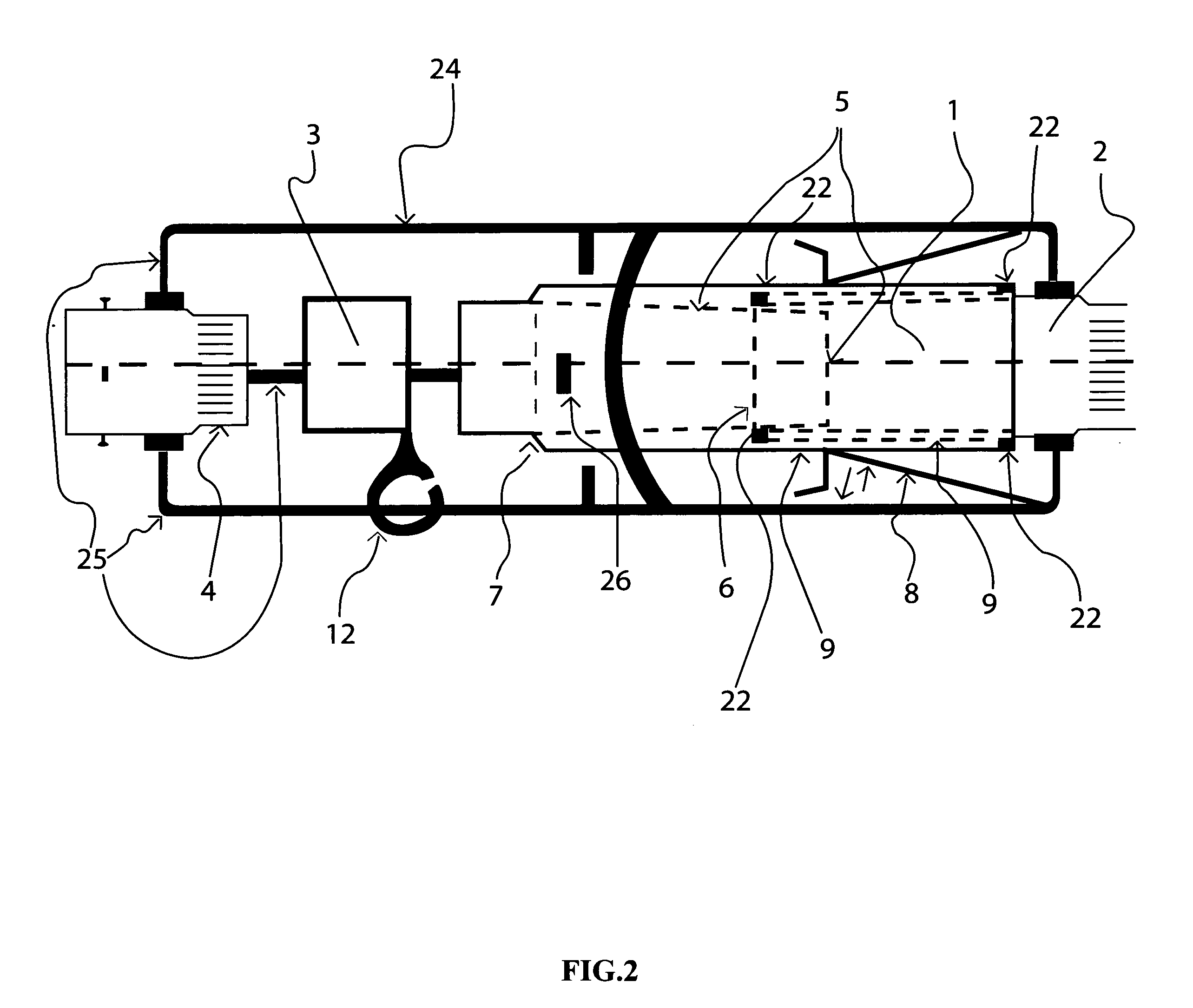
[0031]The present invention is more particularly described in the following examples that are intended as illustrative only. Since numerous modifications and variations there in will be apparent to those skilled in the art. Various embodiments of the invention are now described in detail. Referring to the drawings, like numbers indicate like parts throughout the views. As used in the description herein and throughout the claim that follows. The meaning of “a”, “an”, and “the”, includes plural reference unless the context clearly dictates otherwise. Also as used in the description herein and throughout the claim that follows, the meaning of “in”, includes “in” and “on” unless the context clearly dictates otherwise. Also, in the construction of the invention, all parts are attached by way of either welding and rivets and threaded nuts that attach the frame parts.

[0032]The description shall be made as to the embodiments of the present invention in conjunction with the accompanying draw...


PUM


Abstract

The “Chimney Cap Link”, a device that when used will conserve heat in a dwelling. Installed between the stove pipe and the wall connection, it serves to enable one to, in only seconds, install or remove an insulated double wall cap. To be done regularly, without any leakage when wood stove or similar appliance is in use, and done cleanly with ease.
Having a sliding lock seal, the prototype is framed using one half (½) inch steel rod and nuts. Rivets and sealant is used to join the one third (⅓) length parallel walls to the two primary pipes. Welding may be a better option or one piece pipe parts. The sliding seal reveals an open gap in the pipe, in order to insert or remove the insulated cap.
Therefore, when used, the cap stops heat from escaping out the hole in the wall and prevents cold air from entering the dwelling. Also during the hot summer months, when air conditioners are in use, the insulated cap performs the opposite function, it caps the heat out and prevents the inner cool air from escaping out the hole.
When regularly used the “Chimney Cap Link” performs its duty 24 hours a day, and saves on energy 24 hours per day.

Description

FIELD OF THE INVENTION[0001]The present invention generally relates to a wood or combustion stove or furnace installation, and more particularly, to a frame mounted slidable pipe link assembly and its utility in providing quick access to an open flue, and by means by which the flue may be rapidly coupled to a stove or other combustion device.BACKGROUND OF THE INVENTION[0002]Combustion heating units, such as furnaces or stoves, whether utilizing wood or other forms of fuel to generate heat, all require a smoke evacuation conduit, a flue pipe leading to a chimney, is common place.It is such that these are popular devices for heating in residential and commercial buildings.[0003]When such a unit is not in use, however, the opening within the unit, connected to a flue leading outside forms a passage, through which heated air or cooled air can escape from the interior of the building.A frame mounted slidable pipe link assembly, providing instant access to a flue, when it is not in use, s...

Claims


Application Information

Patent Timeline
Patent Type & Authority Applications(United States)
IPC IPC(8): F23L11/00F23J13/04F23J13/08
CPCF23L11/005F23J13/04F23J13/08F23J2213/204F23J2213/50
Inventor THOMPSON, PETER, ROMAIN
Owner THOMPSON PETER ROMAIN
Why Eureka
Try Eureka