Image module package and manufacturing method thereof

Active Publication Date: 2016-02-11
PIXART IMAGING INC
View PDF12 Cites 23 Cited by
  • Summary
  • Abstract
  • Description
  • Claims
  • Application Information

AI Technical Summary

Benefits of technology

[0009]The present disclosure provides an image module package and a manufacturing method thereof that may simplify the manufacturing process and eliminate the mechanical damage to a sensing surface thereof.
[0010]The present disc

Problems solved by technology

However, inventors note that if the glass filter 93 is directly disposed on the sensing surface, the sensing

Method used


Image

  • Image module package and manufacturing method thereof
  • Image module package and manufacturing method thereof
  • Image module package and manufacturing method thereof

Examples


Example

[0018]It should be noted that, wherever possible, the same reference numbers will be used throughout the drawings to refer to the same or like parts.

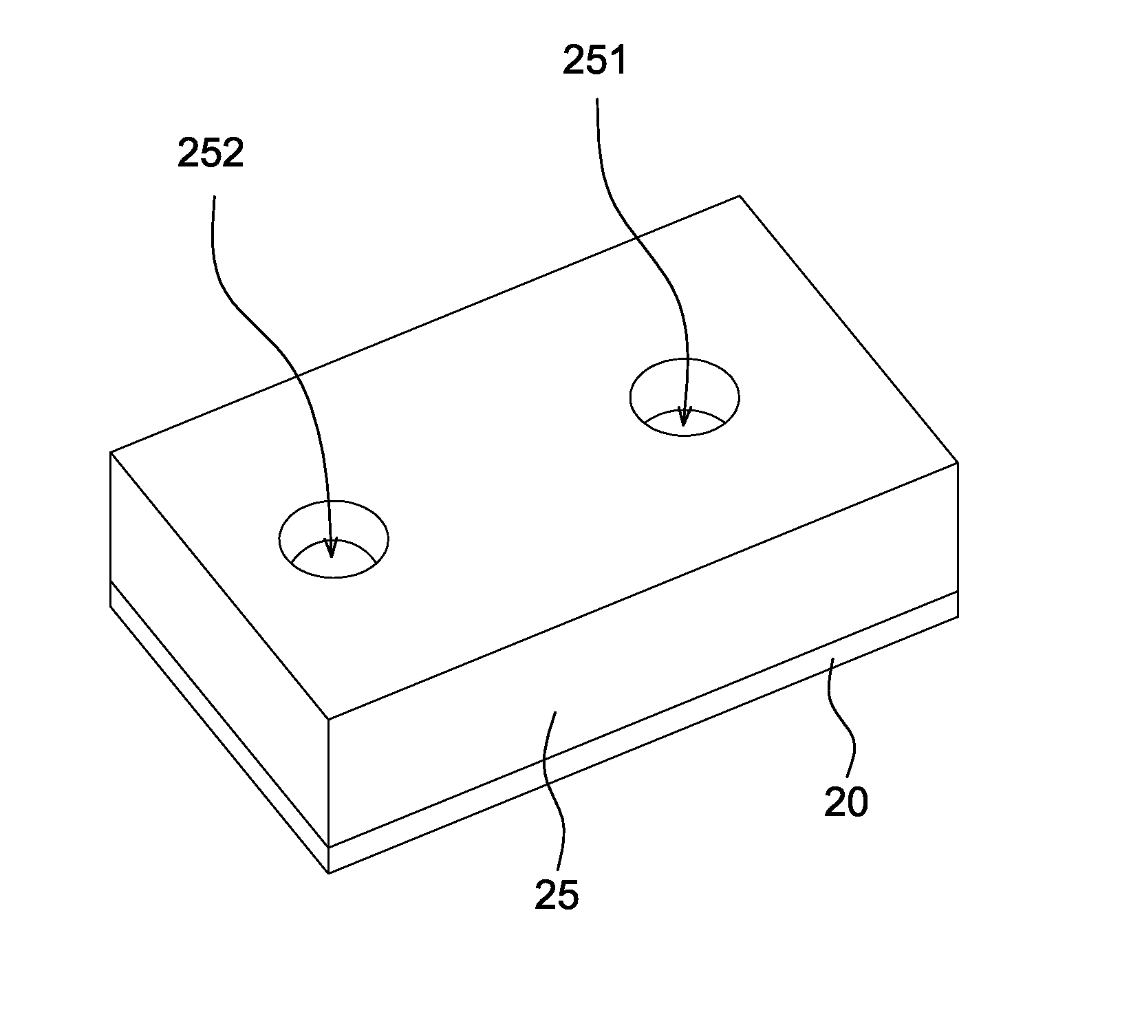
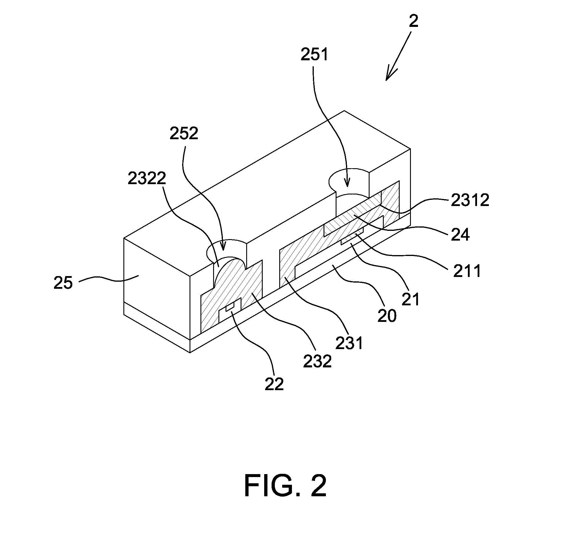
[0019]Referring to FIG. 2, it is a cross-sectional view of the image module package 2 according to one embodiment of the present disclosure. The image module package 2 includes a substrate 20, a photo sensor chip 21, a light emitting die 22, a first molded transparent layer 231, a second molded transparent layer 232, a glass filter 24 and an opaque layer 25. In the image module package 2, the light emitting die 22 is configured to illuminate an object (not shown) and the photo sensor chip 21 is configured to receive reflected light from the object and convert the reflected light to electrical signals, wherein the object is, for example, a finger. In one embodiment, the photo sensor chip 21 directly performs the post-processing according to the converted electrical signals, e.g. calculating the object distance or ambient light intensity....


PUM


Abstract

There is provided an image module package including a substrate, a photo sensor chip, a molded transparent layer and a glass filter. The substrate has an upper surface. The photo sensor chip is attached to the upper surface of the substrate and electrically connected to the substrate. The molded transparent layer covers the photo sensor chip and a part of the upper surface of the substrate, wherein a top surface of the molded transparent layer is formed with a receptacle opposite to the photo sensor chip. The glass filter is accommodated in the receptacle.

Description

BACKGROUND[0001]1. Field of the Disclosure[0002]This disclosure generally relates to an image module package and, more particularly, to an image module package and a manufacturing method thereof with a sub-assembly made by an over-molding process or a casting process.[0003]2. Description of the Related Art[0004]Light sensor modules, such as proximity sensors, ambient light sensors and color sensors generally detect light energy of a predetermined spectrum and output detected signals for post-processing by a processor.[0005]In order to detect the predetermined spectrum, an organic or an inorganic filtering layer can be directly coated on a sensing surface of the photo sensor chip thereof, or a glass filter can be attached to the sensing surface.[0006]For example, FIG. 1 is a solid diagram of the conventional light sensor module which includes a substrate 90. A photo sensor chip 91 and a light source 92 are disposed on the substrate 90, wherein the light source 92 is configured to ill...

Claims


Application Information

Patent Timeline
IPC IPC(8): G01J1/02G01S17/04H01L25/00H01L25/16
CPCG01J1/0271H01L25/167H01L25/50G01J1/0214H01L2924/0002G01J3/0227G01J3/0256G01J3/108G01J3/0262H01L2924/00G01S7/4813G01S17/04
Inventor T'NG, CHEE-PINLEE, SAI-MUN
Owner PIXART IMAGING INC
Why Eureka
Try Eureka