Testing fiber arrangement in multi-fiber cables

a multi-fiber array and fiber arrangement technology, applied in the direction of testing fibre optic/optical waveguide devices, transmission, structural/machine measurement, etc., can solve the problems of insufficient olts measurement, poor polarity of multi-fiber array connections, and failure to meet the needs of users, so as to minimize the risk of user connection errors and minimize the wear of connectors

Active Publication Date: 2016-02-11
EXFO
View PDF5 Cites 55 Cited by
  • Summary
  • Abstract
  • Description
  • Claims
  • Application Information

AI Technical Summary

Benefits of technology

[0028]In a further embodiment, the optical reflectometry acquisition device, the optical switch and the signature array are integrated and interconnected in a portable test instrument. The intergration minimizes the risk of user connection errors and also minimizes wear of connectors resulting from repeated connection and disconnection of optical components together. The most expensive parts of the optical reflectometry system (i.e. the optical reflectometry acquisition device, the optical switch and the signature array) are then permanently connected inside the portable test instrument, which prevents the optical connectors interconnecting these parts from wear due to connections and disconnections.

Problems solved by technology

Hence, deployment mistakes can easily occur if the appropriate arrangement of cable types is not followed (e.g. some cables are mixed up) which result in improper fiber polarity at the multi-fiber array connections.
But even when employing the Universal Polarity Management Method by Corning™, deployment mistakes may arise if the wrong cable types or optical fiber transition modules are installed.
These measurements may be performed with an Optical Loss Test Set (OLTS), but OLTS measurements are not sufficient for Tier 2 testing which, in addition to encompassing those measurement associated with Tier 1 testing, further require a complete characterization of the various elements along a fiber link.
As a consequence, this geometry mismatch between spliced or otherwise connected fibers may cause an apparent “gain” or a drop in the backscattered light of OTDR measurements, which introduces a bias in the insertion loss measurement.
An OTDR measurement performed from the opposite end on the same fiber connection would conversely result in an overestimation of the connection loss.
For this reason, the precision obtained with single-end OTDR measurements may not always be sufficient for Tier 1 and / or Tier 2 testing requiring characterization of optical fiber connections and / or overall insertion loss.
Furthermore, in certain cases, it may also provide insertion loss measurements on each individual optical fiber of the MPO cable.
However, in practice, these rules may be applied to more loopbacks for redundancy.

Method used


Image

  • Testing fiber arrangement in multi-fiber cables
  • Testing fiber arrangement in multi-fiber cables
  • Testing fiber arrangement in multi-fiber cables

Examples


embodiment 550

[0091]Of course, it will be understood that, similarly to the embodiment of FIG. 5A, the input and / or output MPO connectors 554, 556 of the embodiment 550 of FIG. 5B could be replaced by angled-polished physical contact (e.g. FC / APC connectors) and the corresponding event features E1X / E3X be replaced by non-angle polished physical contact connectors (such as FC / PC connectors) inserted along the optical fiber paths 552 to produce the three event features (E1X, E2X and E3X) such that the optical distance L between event feature E1X and event feature E3X is the same for all the signatures.

[0092]It is also noted that if the signature array 500 of FIG. 5A is to be integrated inside test instrument (such as in the test instrument 418), event features E1X could be replaced by the use of a non-angled polished (e.g. FC / PC) at the input MPO connector 504.

[0093]It will be understood that other configurations of signature arrays may be used instead of the signature arrays 500, 550 of FIGS. 5A a...

first embodiment

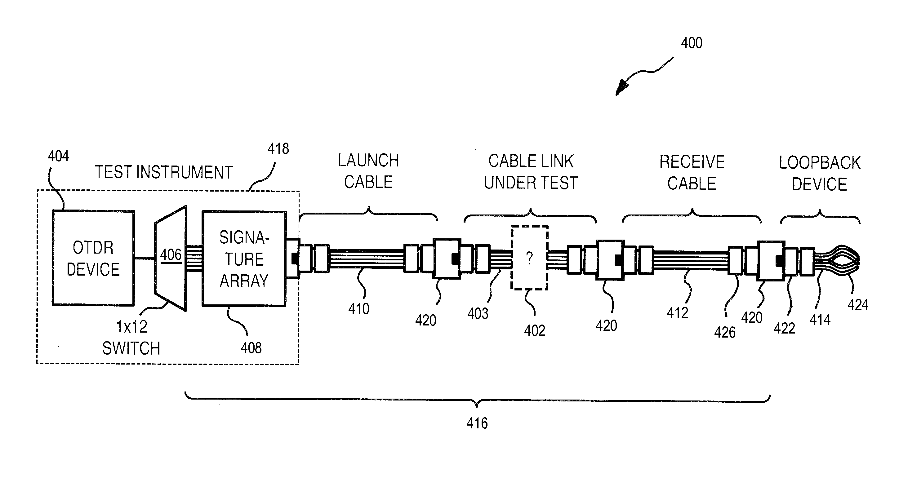
[0100]FIG. 6A schematically illustrates a loopback device 600 and the corresponding test configuration comprising the signature array 408, the launch cable 410, the cable link under test 402, the receive cable 412 (see FIG. 4) and the loopback device 600. The combination of the signature array 408, the launch cable 410, the cable link under test 402 and the receive cable 412 defines a plurality (in this case 1×12) of optical fiber links 416 on which OTDR acquisitions are to be undertaken using the OTDR system 400 of FIG. 4. The loopback device 600 may be employed for example with the signature array 500 of FIG. 5A for testing a fiber arrangement of the cable link under test 402.

[0101]The loopback device 600 comprises an input MPO connector 602 and six loops 604 of optical fiber that each couple one port of the input MPO connector 602 to another. The length of the six loops are typically similar to that of launch and receive cables (i.e. about 10 to 25 m for testing “premises” optica...

second embodiment

[0107]FIG. 7A schematically illustrates a loopback device 700 and the corresponding test configuration comprising the signature array 408, the launch cable 410, the cable link under test 402, the receive cable 412 (see FIG. 4) and the loopback device 700. In this embodiment, port 1 is coupled back to port 12, port 2 is coupled back to port 3, port 4 is coupled back to port 11, port 5 is coupled back to port 8, port 6 is coupled back to port 9 and port 7 is coupled back to port 10, as shown in Table 4. In this embodiment, the optical fiber loops 604 are also of equal length.

TABLE 4Loopback configuration of loopback device 700 of FIG. 7A112233241158697108596107114121

[0108]The plurality of optical fiber ports of the input MPO connector 702 of the loopback device 700 has alternating even- and odd-numbered optical fiber ports (corresponding to the alternating Rx and Tx polarities in the case of a duplex multi-fiber array configuration). In the embodiment of FIG. 7A, each optical fiber lo...


PUM


Abstract

There is provided a method and a system for identifying or verifying the fiber arrangement and/or the cable type of multi-fiber array cables (such as MPO cables) which employs an OTDR acquisition device at the near end of the MPO cable, a loopback device at the far end and an array of signatures detectable by the OTDR, either at the far or the near end. The loopback device allows performing bidirectional OTDR measurements with a single OTDR acquisition device (without moving it from one end to the other) and the signature array provides fiber arrangement/cable type identification or verification.

Description

CROSS-REFERENCE TO RELATED APPLICATIONS[0001]This application claims priority under 35 USC §119(e) of U.S. provisional patent application 62 / 034,533 filed Aug. 7, 2014; the specification of which is hereby incorporated by reference.TECHNICAL FIELD[0002]The invention relates to the characterization of multi-fiber array cables and more specifically to identifying or verifying the fiber arrangement of a multi-fiber array cable using optical time-domain reflectometry.BACKGROUND OF THE ART[0003]Optical reflectometric methods are widely employed for characterization of optical fiber links. Among these methods, the most commonly used approach is Optical Time-Domain Reflectometry (OTDR—also used to refer to the corresponding device), a diagnostic technique where light pulses are launched in an optical fiber link and the returning light, arising from backscattering and reflections along the fiber link, is detected and analyzed. Various “events” along the fiber link can be detected and charac...

Claims


Application Information

Patent Timeline
Patent Type & Authority Applications(United States)
IPC IPC(8): G01M11/00H04B10/071
CPCG01M11/3136H04B10/071G01M11/3154
Inventor L'HEUREUX, MARIOPERRON, STEPHANELECLERC, MICHEL
Owner EXFO
Why Eureka
Try Eureka