Temperature adjustment device

a technology of temperature adjustment device and temperature adjustment device, which is applied in the direction of electrical equipment, vehicle components, propulsion parts, etc., can solve the problems of limited vertical dimension of the portion below the rear seats, and achieve the effect of reducing the size increasing the living space, and reducing the dimension of the power storage apparatus

Active Publication Date: 2016-02-11
CALSONIC KANSEI CORP
View PDF4 Cites 7 Cited by
  • Summary
  • Abstract
  • Description
  • Claims
  • Application Information

AI Technical Summary

Benefits of technology

[0008]With the temperature adjustment device according to the above-mentioned aspect, an inlet connecting member and an outlet connecting member are configured such that pipe pathways are flat, and the inlet connecting member and the outlet connecting member are laminated and arranged on the lower surface of the cooling member, and thereby, the cooling medium is supplied / discharged to / from the lower surface of the cooling member. With the temperature adjustment device according to the above-mentioned aspect, it is possible to make the dimensions of the inlet connecting member and the outlet connecting member in the vertical direction small. In combination with the fact that limitation caused to the thicknesswise dimension of the cooling member by the respective the dimensions of the inlet connecting member and the outlet connecting member in the vertical direction is reduced, it is possible to make the dimension of the temperature adjustment device in the vertical direction small. As a result, it is possible to reduce the size of a power storage apparatus by reducing the dimension of the power storage apparatus in the vertical direction of a vehicle, thereby making it possible to increase a living space in a cabin (a space at rear seats).

Problems solved by technology

A dimension of the portion below the rear seats in the vertical direction is limited due to the limitation with regard to a height dimension from a floor surface.

Method used


Image

  • Temperature adjustment device
  • Temperature adjustment device
  • Temperature adjustment device

Examples


first embodiment

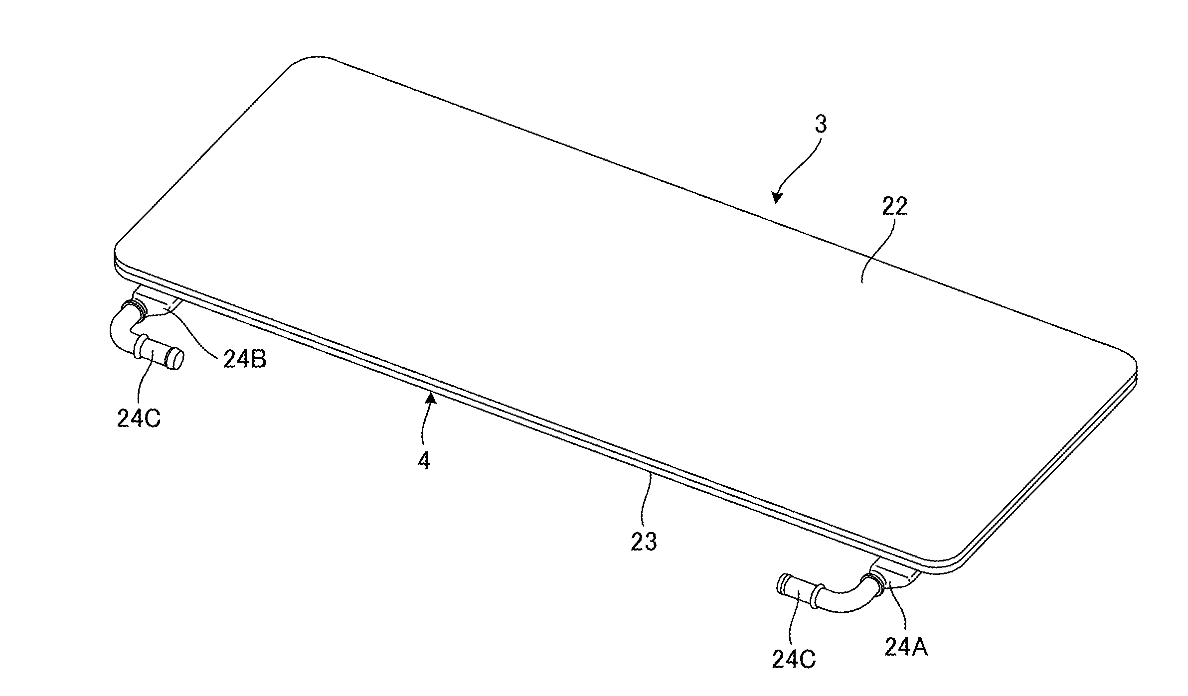
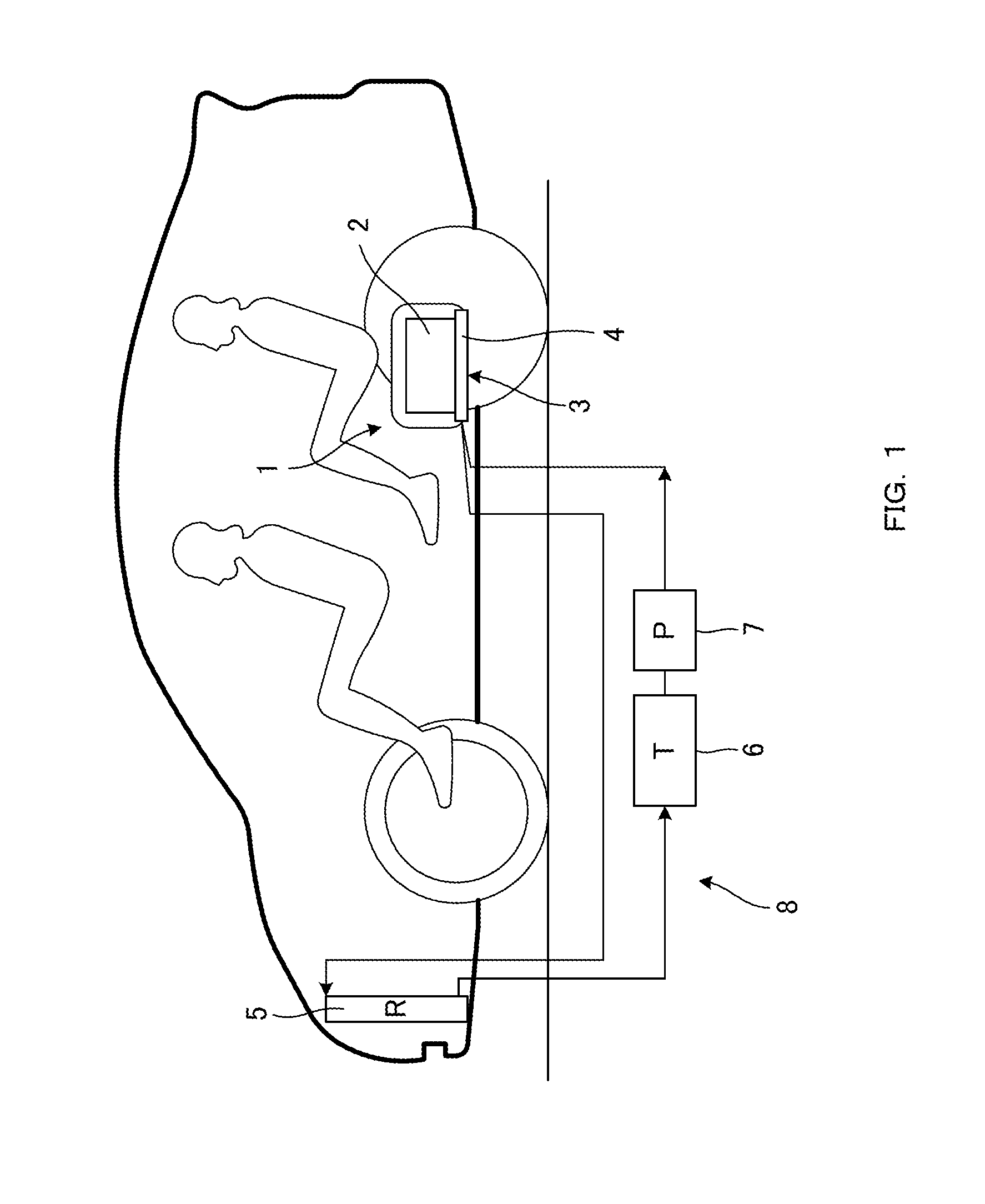
[0026]As shown in FIG. 1, a power storage apparatus 1 is arranged between a lower surface of a seat cushion of rear seats of a vehicle and a floor of a vehicle body. The power storage apparatus 1 supplies power to a motor generator that serves as a driving source for running an electric car. The power storage apparatus 1 consists of a plurality of battery modules 2 and a temperature adjustment device 3. Electric power is stored in the plurality of battery modules 2. The temperature adjustment device 3 adjusts temperature of the plurality of battery modules 2 with a cooling member 4 that is thermally in contact with the bottom surfaces of the plurality of battery modules 2. A cooling efficiency may be improved by providing a heat-conducting member between the bottom surfaces of the battery modules 2 and the cooling member 4.

[0027]The cooling member 4 constitutes the temperature adjustment device 3. An interior of the cooling member 4 is made hollow. The temperature adjustment device ...

second embodiment

[0058]FIG. 14 is a diagram showing the power storage apparatus 1 including the temperature adjustment device according to the second embodiment in a disassembled state. FIG. 15 a diagram showing the power storage apparatus 1 including the temperature adjustment device according to the second embodiment in a state in which the power storage apparatus 1 is mounted to a vehicle body member. FIG. 16 is a view taken along an arrow Y in FIG. 15. In this embodiment, the temperature adjustment device 3 is arranged below the battery case 10. Components that are the same as or equivalent to those in the first embodiment are given the same reference signs, and descriptions thereof will be omitted or simplified.

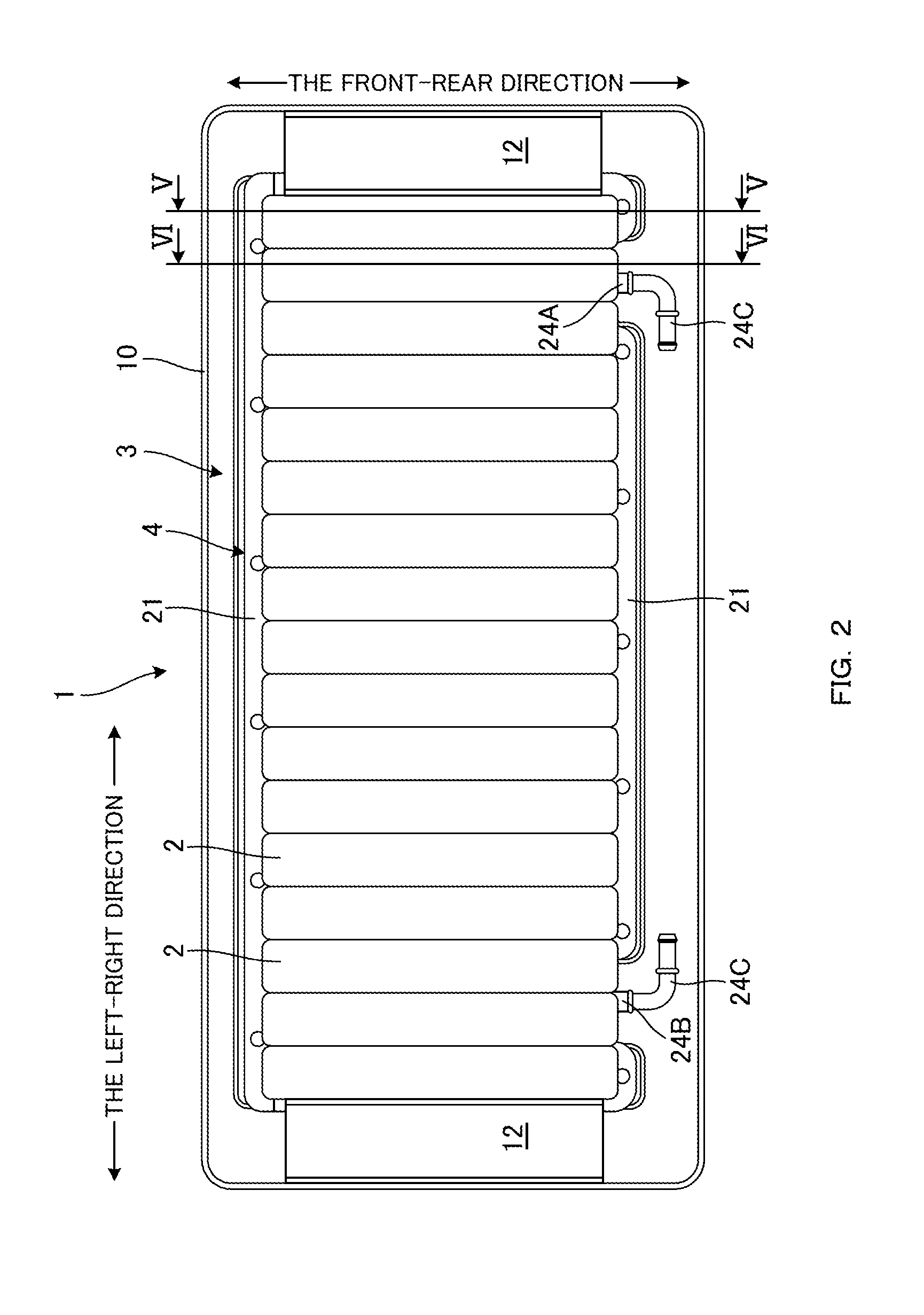
[0059]As shown in FIG. 14, with the power storage apparatus 1 in this embodiment, the plurality of battery modules 2 are directly accommodated in the battery case 10 so as to be arrayed in the left-right direction. Next, the temperature adjustment device 3 is attached to the battery case...


PUM

PropertyMeasurementUnit
temperatureaaaaaaaaaa
diameteraaaaaaaaaa
heightaaaaaaaaaa

Abstract

A temperature adjustment device includes a cooling member and a connecting member. The cooling member consists of a first plate and a second plate. The first plate is thermally abutted against a heat-generating member. The second plate is stacked on a lower surface of the first plate to define a cooling space with the first plate, the cooling space a cooling medium flows through, and being configured to include an inlet and an outlet of the cooling medium on a bottom surface facing against the first plate. The connecting member is the connecting member to a temperature adjustment circuit, and that is configured with a tube member having a flat part. The connecting member includes a connecting port connected to the inlet or the outlet on the flat part, and that is laminated and arranged on the second plate such that the flat part is abutted against the second plate.

Description

TECHNICAL FIELD[0001]The present invention relates to a temperature adjustment device.BACKGROUND ART[0002]A power storage apparatus including a cooling member for adjusting temperature of a plurality of battery modules by thermally abutting against bottom surfaces of the plurality of battery modules and by utilizing a cooling medium flowing through the interior thereof has been recently proposed. The battery modules consist of assemblies of a plurality of battery cells.[0003]In a technique disclosed in JP2012-156124A, an inflow port and an outflow exit for a cooling medium formed of tube members are provided on a side surface of a cooling member, and the inflow port and the outflow exit are connected to a temperature adjustment circuit including a pump, a tank and a radiator. The cooling medium is then circulated between the temperature adjustment circuit and the cooling member to cool the cooling member, thereby adjusting the temperature of the heat-generating battery modules at th...

Claims


Application Information

Patent Timeline
Patent Type & Authority Applications(United States)
IPC IPC(8): H01M10/613B60K11/02H01M10/625H01M10/6556
CPCH01M10/613B60K11/02H01M10/6556H01M10/625H01M10/6568H01M10/66Y02E60/10
Inventor KAWAGUCHI, TATSUNARIOTSUKA, TAKASHIMOTOHASHI, TOSHIYUKISAKUMA, SATOSHI
Owner CALSONIC KANSEI CORP
Why Eureka
Try Eureka