
Device cover for thermal management

a technology for thermal management and devices, applied in the direction of circuit thermal arrangement, cooling/ventilation/heating modification, printed circuit details, etc., can solve the problems of heat generation, increased functionality and device complexity, and significant challenges in thermal management, and achieve the effect of removing a larger amount of component-generated heat via radiation and high emissivity

Active Publication Date: 2016-02-11
INTERDIGITAL MADISON PATENT HLDG SAS
View PDF8 Cites 13 Cited by
  • Summary
  • Abstract
  • Description
  • Claims
  • Application Information

AI Technical Summary

Benefits of technology

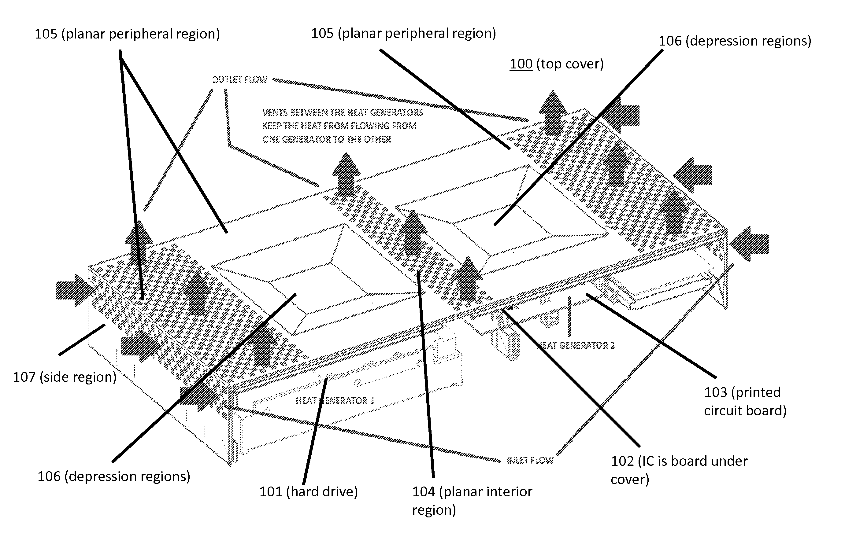
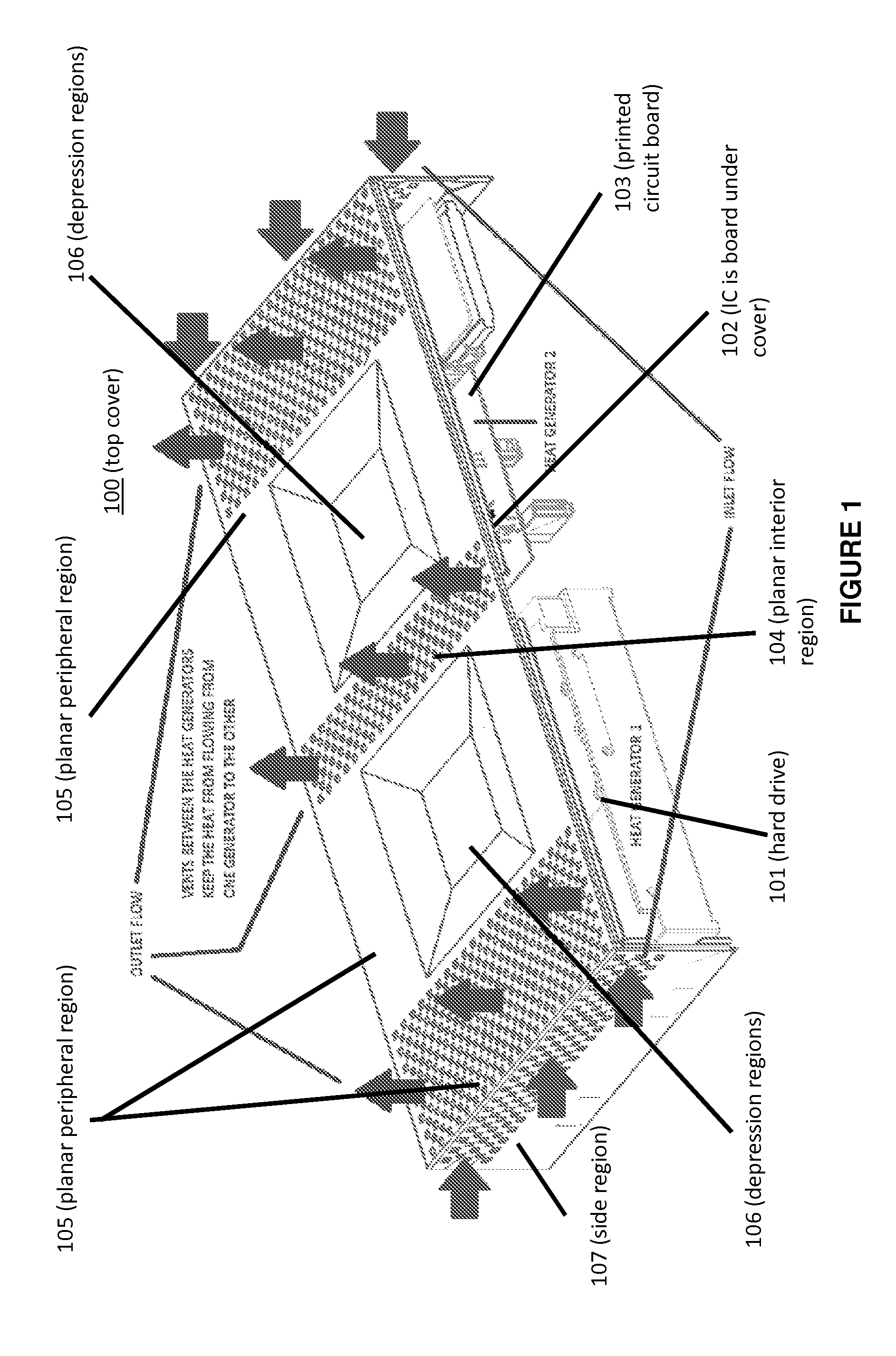
The present invention provides an apparatus for cooling heat-generating components using a cover or enclosure with conductive, convective, and radiant cooling. The cover has depression regions that are thermally coupled to the components, and air inlets and outlets are strategically placed for effective cooling. The cover can also be painted or treated to achieve a high emissivity value for increased heat transfer. The technical effect is to maintain the apparatus within a prescribed temperature range and to improve heat transfer efficiency.

Problems solved by technology

Thermal management remains a significant challenge in consumer devices such as set top boxes and the like.
As set top boxes, for example, exhibit increased functionality and device complexity with the introduction of additional components such as smart card readers, more heat is generated by and introduced into the device.
Thermal management becomes more challenging in the face of pressures to miniaturize and reduce the size of set top boxes due to consumer preference.
Not only is the realization of an effective thermal management system challenging for these devices such as set top boxes, but it represents a further expense over the basic costs for the enclosure (i.e., cover) and the components themselves.

Method used


Image

  • Device cover for thermal management
  • Device cover for thermal management

Examples


Embodiment Construction

[0014]The present description illustrates the principles of the present invention for thermal management of a device or apparatus. It will thus be appreciated that those skilled in the art will be able to devise various arrangements that, although not explicitly described or shown herein, embody the principles of the disclosure and are included within its spirit and scope.

[0015]Apparatus and techniques providing one or more depression regions in a heat sink that is enclosed by a separate device cover have been presented in detail in several co-pending patent applications assigned to the common assignee hereof. The co-pending applications, which are incorporated by reference herein in their entirety, are:[0016]U.S. patent application Ser. No. 13 / 580,482 published as U.S. Patent Application Publication No. 2012 / 0307455 entitled, “Miniature Multilayer Radiative Cooling Case With Hidden Quick Release Snaps”; and[0017]PCT Patent Application No. PCT / US2012 / 028000 published as Internationa...


PUM


Abstract

An electronic device includes a cover for one or more heat generating components, with the cover providing at least a combined conductive, convective, and radiant cooling for the heat generating components while maintaining the device within a prescribed temperature range. Conductive cooling is realized by providing thermal coupling between each of two or more depression regions in the cover and one or more heat generating components. Appropriate placement of air inlets and outlets through the cover provides convective cooling of the heat generating components and the thermally coupled depression regions. Heat from the heat generating components thermally coupled to one depression region is effectively isolated from heat generated by other heat generating components thermally coupled to another adjacent depression region at least in part via the air outlets through an interior region between the two adjacent depression regions. Radiant cooling can also be improved by increasing the emissivity of the device cover material.

Description

FIELD OF THE INVENTION[0001]This invention relates to a device having a cover that performs thermal management providing for cooling of internal heat generating components via at least a combination of convective, conductive, and radiant cooling while maintaining the cover within a prescribed temperature range.BACKGROUND OF THE INVENTION[0002]Thermal management remains a significant challenge in consumer devices such as set top boxes and the like. As set top boxes, for example, exhibit increased functionality and device complexity with the introduction of additional components such as smart card readers, more heat is generated by and introduced into the device. That heat needs to be dissipated. In turn, there is a continuing need for an improved thermal management system in such devices.[0003]Thermal management becomes more challenging in the face of pressures to miniaturize and reduce the size of set top boxes due to consumer preference. A greater degree of compactness coupled with...

Claims


Application Information

Patent Timeline
Patent Type & Authority Applications(United States)
IPC IPC(8): H05K7/20
CPCH05K7/20436H05K7/20127H05K1/0203
Inventor PROCTOR, CHRISTOPHER MICHAEL WILLIAMCHEAH, SIN HUINAGANATHAN, GIRISH
Owner INTERDIGITAL MADISON PATENT HLDG SAS
Learn More