Energy Storage System Preventing Self from Overheating, a Method for Preventing Energy Storage System from Overheating and a Method for Forming A Heat Dissipation Coating on Energy Storage System

a technology of energy storage system and self-heating, which is applied in the field of energy storage system, can solve the problems of reducing the operating temperature of the energy storage system and prolonging the life, and achieves the effects of enhancing the emissivity of the entire coating, facilitating the formation of a coating, and high emissivity

Active Publication Date: 2015-07-09
CHNA ENERGY INVESTMENT CORP LTD
View PDF1 Cites 27 Cited by
  • Summary
  • Abstract
  • Description
  • Claims
  • Application Information

AI Technical Summary

Benefits of technology

[0029]Preferably, multiple layers, e.g. 2-4 layers of heat dissipation coating of high emissivity are applied or formed onto at least part of the external surface by the above method. By stacking multiple layers of coating, more interfaces, micro-cracks and / or micro-pores may be introduced therebetween to form a structure which is more favorable for enhancing the emissivity of the entire coating.
[0030]Preferably, each of the coating layer has a curing temperature of 40° C.-100° C., e.g. 50° C. The curing temperature selected from this range may facilitate formation of a coating having a large number of pores and micro-cracks, thereby further intensifying thermal emissivity.
[0031]The formation or application of a heat dissipation coating of high emissivity, such as a heat dissipation coating doped with nano particles or the like, onto an exposed heat dissipating surface of the energy storage system, e.g. the external surface of the terminal posts and / or of the electrical connection straps, endows the exposed heat dissipating surface of the energy storage system with high emissivity which improves heat exchange between the heat dissipating surface and the surroundings to facilitate rapid cooling of the heat dissipating surface and to further reduce the operating temperature of the energy storage system and to prolong lifespan thereof.

Problems solved by technology

This method therefore effectively reduces the operating temperature of the energy storage system and prolongs the lifespan thereof.

Method used


Image

  • Energy Storage System Preventing Self from Overheating, a Method for Preventing Energy Storage System from Overheating and a Method for Forming A Heat Dissipation Coating on Energy Storage System
  • Energy Storage System Preventing Self from Overheating, a Method for Preventing Energy Storage System from Overheating and a Method for Forming A Heat Dissipation Coating on Energy Storage System
  • Energy Storage System Preventing Self from Overheating, a Method for Preventing Energy Storage System from Overheating and a Method for Forming A Heat Dissipation Coating on Energy Storage System

Examples


Embodiment Construction

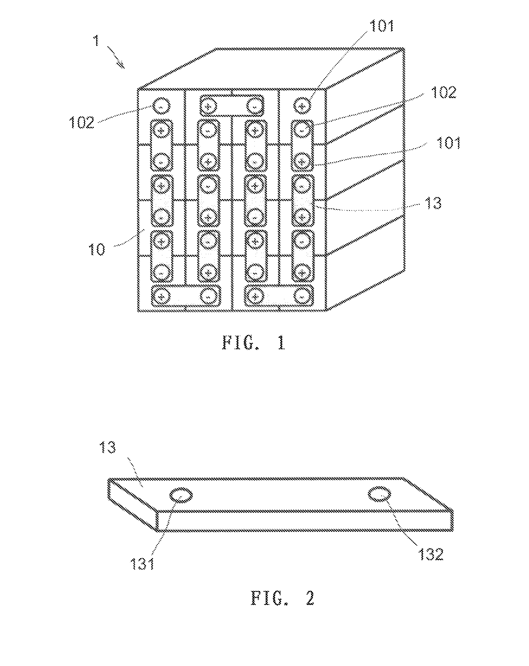
[0042]FIG. 1 is a view of an embodiment of a prior art energy storage system (which is generally referred to as an electrical energy storage system). The energy storage system may be a battery and a system thereof, a capacitor and a system thereof, or other chemical or physical energy storage means. A battery system will be illustrated in detail below as an example. The battery system 1 includes a plurality of battery units (energy storage units) 10, each having one or more cells (energy storage cells). The plurality of battery units 10 may be arranged in any array, and each has two terminal posts 101 (a positive terminal pole post) and 102 (a negative terminal pole post) leading from the interior thereof. An electrical connection between the battery units 10 is done by means of an electrical connection strap (electrical connection element) 13 one end of which is connected to the positive terminal post 101 of one battery unit 10 and the other end of which is connected to the negativ...


PUM

PropertyMeasurementUnit
particle sizeaaaaaaaaaa
temperatureaaaaaaaaaa

Abstract

The present invention discloses an overheat prevention energy storage system preventing self from overheating, comprising a heat dissipating external surface, wherein at least a portion of the external surface is coated with at least one layer of heat dissipation coating of high emissivity. The present invention further discloses a method for preventing overheat of the energy storage system and a method for forming at least one layer of heat dissipation coating of high emissivity onto at least part of an external surface of the energy storage system or assemblies thereof.

Description

TECHNICAL FIELD [0001]The present invention relates to an energy storage system, particularly to a battery and a system thereof, and more particularly to a lead-acid battery and a system thereof, that is capable of preventing self from overheating. The present invention further relates to a method for preventing overheat of the energy storage system and a method for forming at least one layer of heat dissipation coating of high emissivity on at least part of the external surface of the energy storage system or assemblies of the energy storage system.BACKGROUND OF THE INVENTION [0002]As an energy storage system, a battery and a system thereof are means for storing electric energy so as to restore the energy when needed. Typically, a cell includes two electrodes arranged in the electrolyte, i.e. an anode and a cathode. As known in related technologies, an electrical apparatus to be operated is usually connected across the cathode and anode at two ends to obtain electrical energy from ...

Claims


Application Information

Patent Timeline
Patent Type & Authority Applications(United States)
IPC IPC(8): H01M10/6551H01M10/06H01M50/209H01M50/24H01M50/251H01M50/507H01M50/522H01M50/526
CPCH01M10/6551H01M10/06H01M10/613H01M10/6553Y02E60/10H01M50/124H01M50/1245H01M50/522H01M50/507H01M50/526H01M50/209H01M50/251H01M50/24
Inventor JIN, HONGBRILMYER, GEORGE H.NISPEL, MICHAEL T.REN, DONGXUE
Owner CHNA ENERGY INVESTMENT CORP LTD
Why Eureka
Try Eureka