
Sports shoe

a technology for shoes and shoes, applied in the field of shoes, can solve the problems of insufficient performance of shoes according to the prior art, time-consuming and expensive manufacture, and user's need to supply more energy, so as to improve the performance of use, reduce user fatigue, and increase pedaling efficiency

Inactive Publication Date: 2016-02-18
MAVIC SA
View PDF13 Cites 8 Cited by
  • Summary
  • Abstract
  • Description
  • Claims
  • Application Information

AI Technical Summary

Benefits of technology

The invention is a shoe designed to improve pedaling efficiency and reduce user fatigue during sporting events. It aims to make the shoe perform better and reduce the time and cost associated with manufacturing it. The technical effects of the invention are increased efficiency and improved performance in a shoe that works with an apparatus through pedaling.

Problems solved by technology

First, it is a source of fatigue, especially during intense uses, such as in sporting events, for example. In other words, it can be said that the performance of a shoe according to the prior art is insufficient. This means that the user must supply more energy than theoretically required for the use of the apparatus. A reason for this is the overly large gap between the foot and the axis of rotation of the pedal. Indeed, it is known that the closer to the pedal axis the sole of the foot gets, the better the pedaling efficiency will be. Another reason is the relatively substantial weight of the shoe, which has the effect, for example, of increasing its mechanical inertia.
Secondly, a shoe according to the prior art has a complicated structure, thereby making it time-consuming and expensive to manufacture.

Method used


Image

  • Sports shoe
  • Sports shoe
  • Sports shoe

Examples


first embodiment

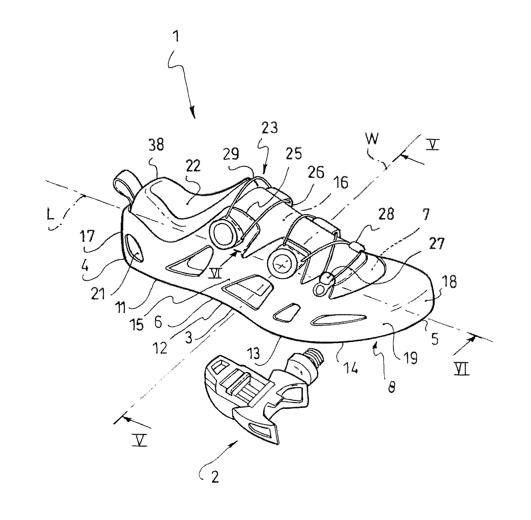
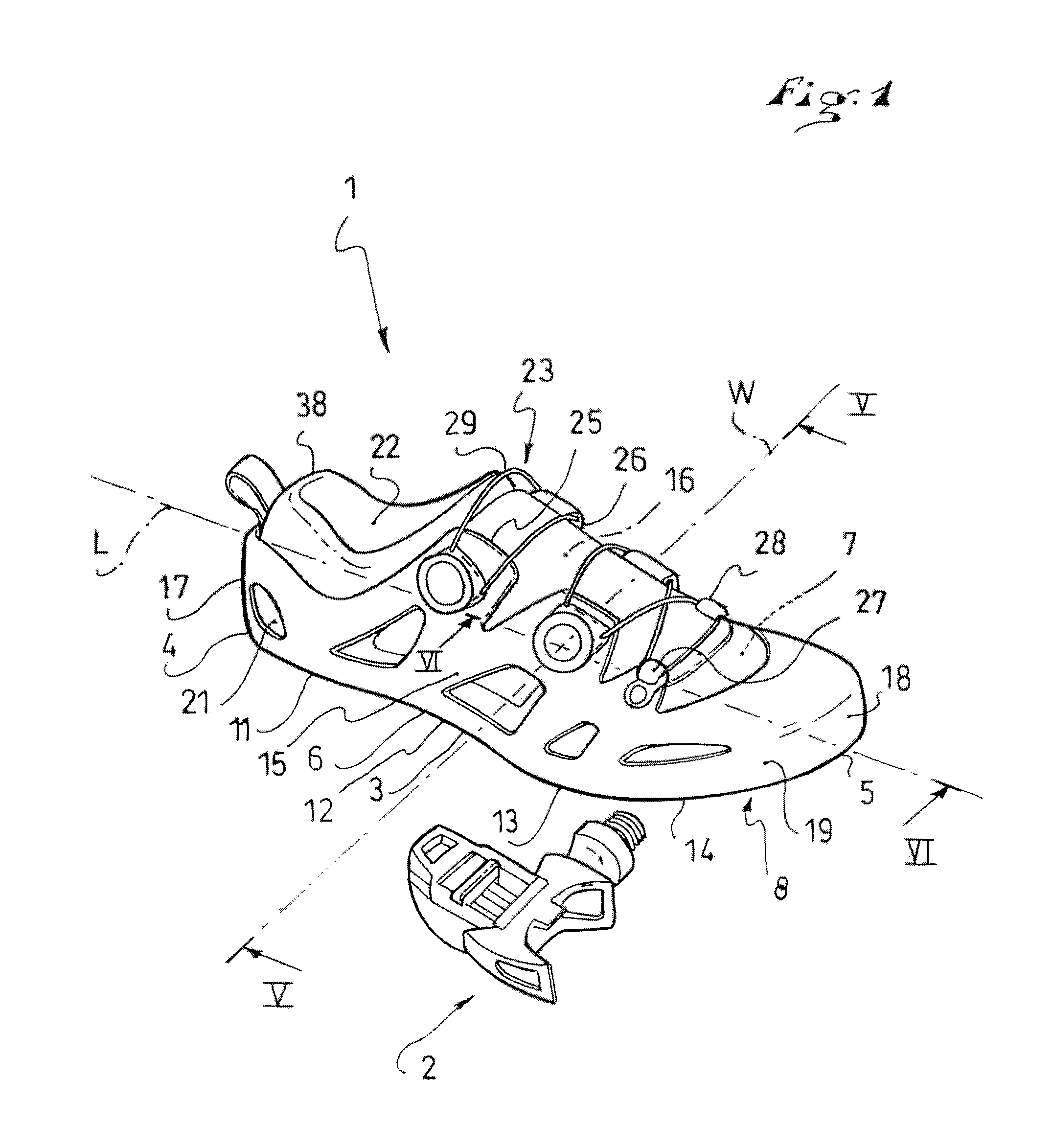
[0033]A first embodiment is described with reference to FIGS. 1 to 7. First, FIG. 1 shows a shoe 1 to receive the foot of the user, and a pedal 2 designed to cooperate with the shoe. The pedal is not further described in detail herein, as it is well-known to one of ordinary skill in the art.

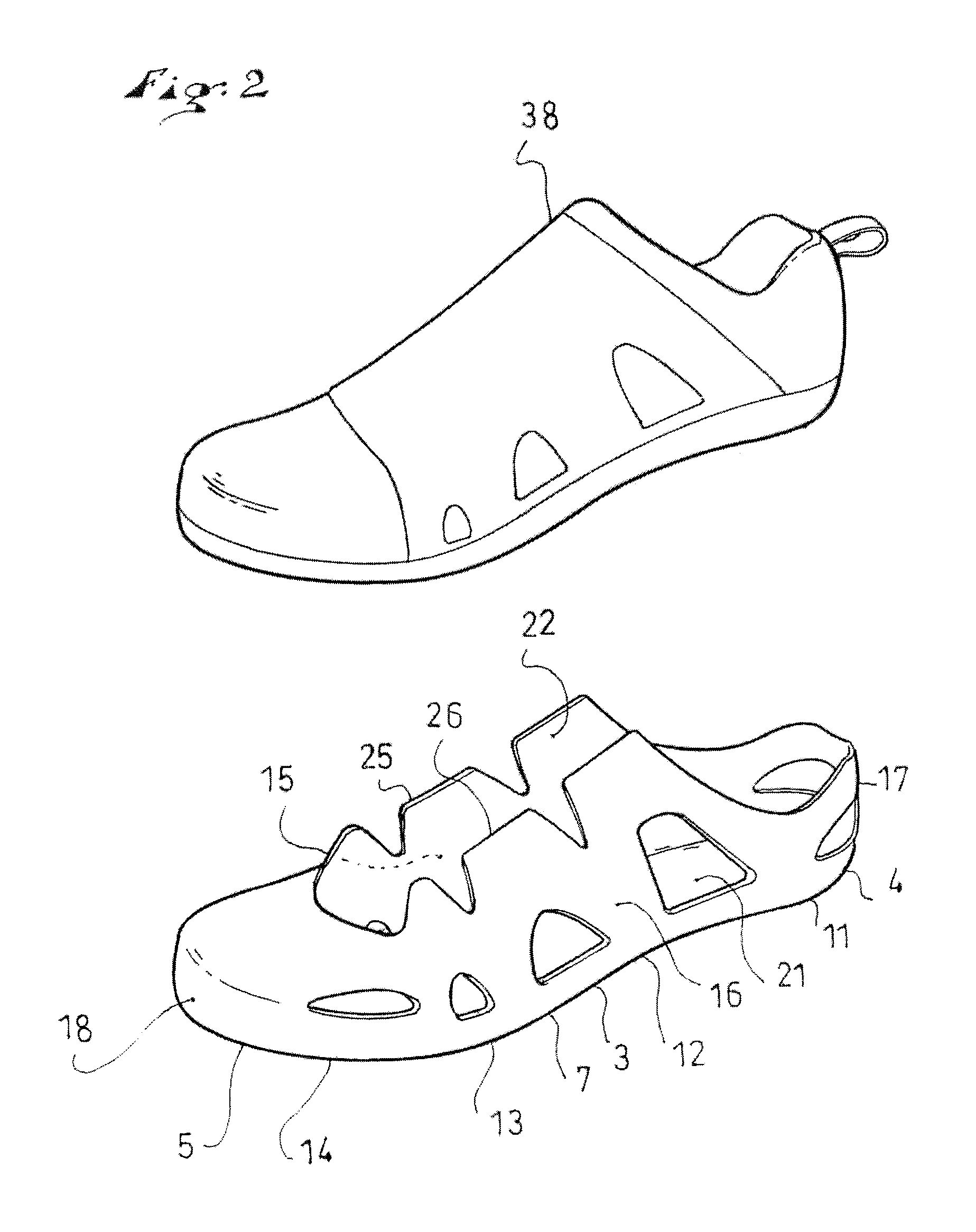
[0034]Conventionally, as can be seen in FIGS. 1 to 4, the shoe 1 comprises a base 3 extending lengthwise along a longitudinal direction L, from a rear end 4 to a front end 5; widthwise along a transverse direction W, between a lateral side 6 and a medial side 7; and depthwise between a surface 8 for cooperation with the apparatus and an inner surface 9. As described below, the cooperation surface 8 can come into contact with the pedal 2 directly or indirectly. Also, the inner surface 9 can come into contact with the foot of the user directly or indirectly, as further described below.

[0035]The base 3 of the shoe, from the rear end 4 to the front end 5, includes a rear zone 11 provided to be opposi...

second embodiment

[0059]Thus, according to FIG. 8, the second embodiment features a shoe 1, with its base 3 and the edges 6, 7, its lateral 15 and medial 16 walls, the cleat 31, and the liner 38.

[0060]What is specific to the second embodiment is the geometry of the cleat 31. Here, the fastening elements 33, 34 follow the longitudinal and transverse convexities for their affixation to the cooperation surface 8, but are within a plane G in the area of contact with the pedal 2. The latter, not shown, has a flat surface for receiving the shoe. This is simply an alternative embodiment which enables the use of a bicycle equipped with flat pedals.

third embodiment

[0061]The third embodiment, according to FIG. 9, also features a shoe 1, with its base 3 and the edges 6, 7, its lateral 15 and medial 16 walls, the cleat 31, and the liner 38.

[0062]What is specific to the third embodiment is that, in the metatarsal zone 13, a spacer 41 is arranged so to be opposite the cooperation surface 8. More specifically, the spacer is interposed between the base 3 and the cleat 31 in the metatarsal zone 13. This spacer protects the cooperation surface 8 from possible mechanical attacks, such as friction or point supports, which could occur, for example, during a cleat position adjustment, during support on the ground or on the pedal, or the like. The spacer 41 can be comprised of a sheet of synthetic material, for example.


PUM


Abstract

A shoe designed to cooperate with an apparatus through a pedaling action, the shoe including a base extending lengthwise from a rear end to a front end, widthwise between a lateral side and a medial side, and depthwise between a surface for cooperating with the apparatus and an inner surface, the base having, from the rear end to the front end, a rear zone, a central zone, a metatarsal zone, and a front zone, the shoe including a lateral wall and a medial wall. The lateral wall and the medial wall are affixed directly to the base, and the base, the lateral wall, and the medial wall are rigid subdivisions of the shoe.

Description

CROSS-REFERENCE TO RELATED APPLICATION[0001]This application is based upon French Patent Application No. FR 14 / 01845, filed Aug. 13, 2014, the disclosure of which is hereby incorporated by reference thereto in its entirety, and the priority of which is claimed under 35 U.S.C. §119.BACKGROUND[0002]1. Field of Invention[0003]The invention relates to a shoe adapted to cooperate with an apparatus through a pedaling action, and relates more particularly to cases in which the apparatus is a vehicle. A shoe according to the invention can be used with a bike, a delivery tricycle, a go-kart, an indoor training machine, or any other apparatus requiring a pedaling action.[0004]2. Background Information[0005]In the field of cycling, for example, the shoe cooperates with a pedal of the apparatus, namely the bike in this case, particularly to make it move forward. The shoe serves, among other functions, to transmit driving or steering forces or impulses, to transmit sensory information, or to ret...

Claims


Application Information

Patent Timeline
Patent Type & Authority Applications(United States)
IPC IPC(8): A43B5/14A43C15/16
CPCA43C15/16A43B5/14A43B3/16A43B13/026
Inventor DELGORGUE, GERALDJOURDE-AUTIER, JACQUES
Owner MAVIC SA
Learn More