
Method of controlling automatic transmission for reducing synchronization shock during upshift in accelerated state

a technology of automatic transmission and synchronization shock, which is applied in the direction of mechanical equipment, digital data processing details, instruments, etc., can solve the problems of reducing the actual speed change range, reducing the engine torque, and often bringing synchronization shock, so as to reduce synchronization shock and minimize synchronization shock

Inactive Publication Date: 2016-02-18
HYUNDAI MOTOR CO LTD
View PDF0 Cites 0 Cited by
  • Summary
  • Abstract
  • Description
  • Claims
  • Application Information

AI Technical Summary

Benefits of technology

This patent text is about a method for controlling an automatic transmission in a car to reduce the shock experienced when shifting between gears in a short period of time. The technical effect of this method is that it minimizes the discomfort experienced during gear shifts in an accelerated state.

Problems solved by technology

Accordingly, since a vehicle with the hybrid system has a greater rotational inertia compared to a typical AT vehicle, shock is often brought during synchronization.
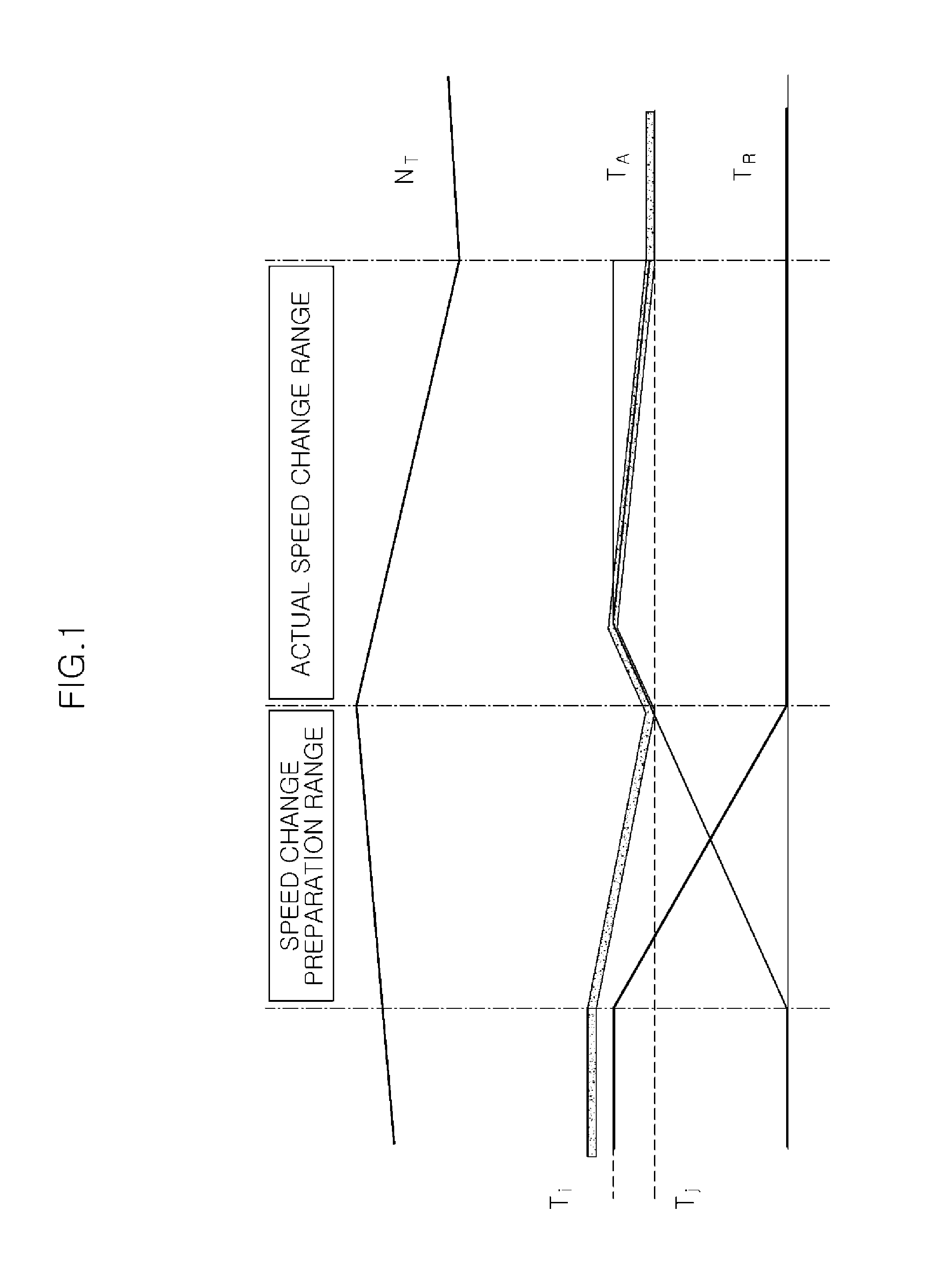
In this case, the actual speed change range may, however, be excessively longer since the turbine rotational speed Nt in the actual speed change range has a functional relation of the shared torque and input torque of the coupling clutch.
However, the decrease of the engine torque or the increase of the shared torque of the coupling element in the synchronization part is eventually present in only a direction in which the turbine is pulled downward.
In this case, since the control measure is not a control measure of depending on repeated data about the amount and time for lowering the shared torque and following the target, the control measure may not be satisfied or vulnerable to disturbance.
These problems may be obviously exhibited in a situation in which the characteristic of operating mechanism is poor as in a low-temperature hydraulic system or in a case of a hybrid system in which the moment of rotational inertia of a transmission input shaft is great.
In addition, the hybrid system with the TMED is difficult to obtain a good shift feeling since the response of the operating mechanism is slow when the performance of the operating mechanism is delayed in a specific situation as in the low-temperature hydraulic system and thus the synchronization is uneven.
That is, there is a limit to the method of reducing synchronization shock since the speed change range is controlled only by the coupling element together with the decrease of the torque as in the related art.

Method used


Image

  • Method of controlling automatic transmission for reducing synchronization shock during upshift in accelerated state
  • Method of controlling automatic transmission for reducing synchronization shock during upshift in accelerated state
  • Method of controlling automatic transmission for reducing synchronization shock during upshift in accelerated state

Examples


Embodiment Construction

[0025]Reference will now be made in detail to various embodiments of the present invention(s), examples of which are illustrated in the accompanying drawings and described below. While the invention(s) will be described in conjunction with exemplary embodiments, it will be understood that the present description is not intended to limit the invention(s) to those exemplary embodiments. On the contrary, the invention(s) is / are intended to cover not only the exemplary embodiments, but also various alternatives, modifications, equivalents and other embodiments, which may be included within the spirit and scope of the invention as defined by the appended claims.

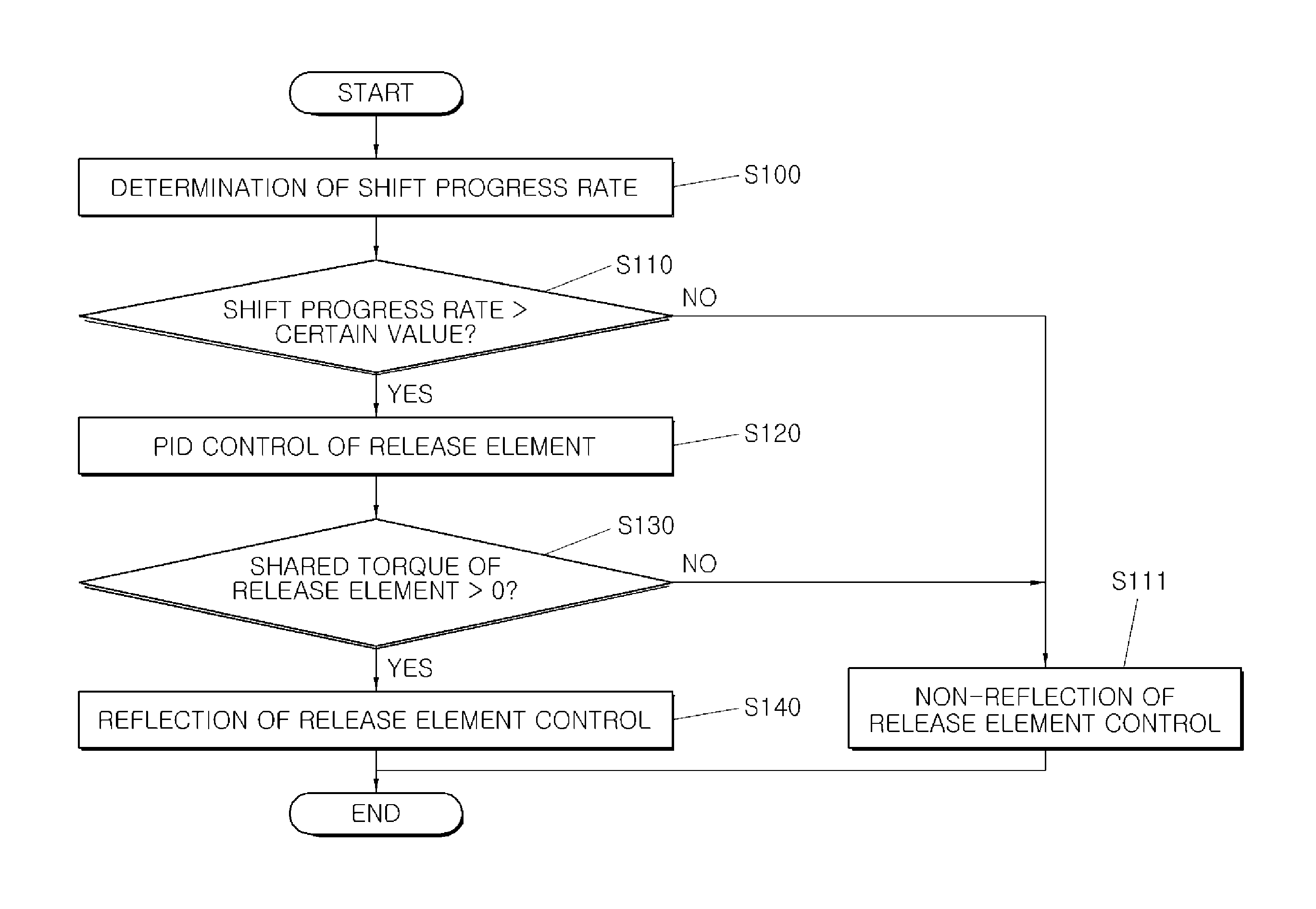
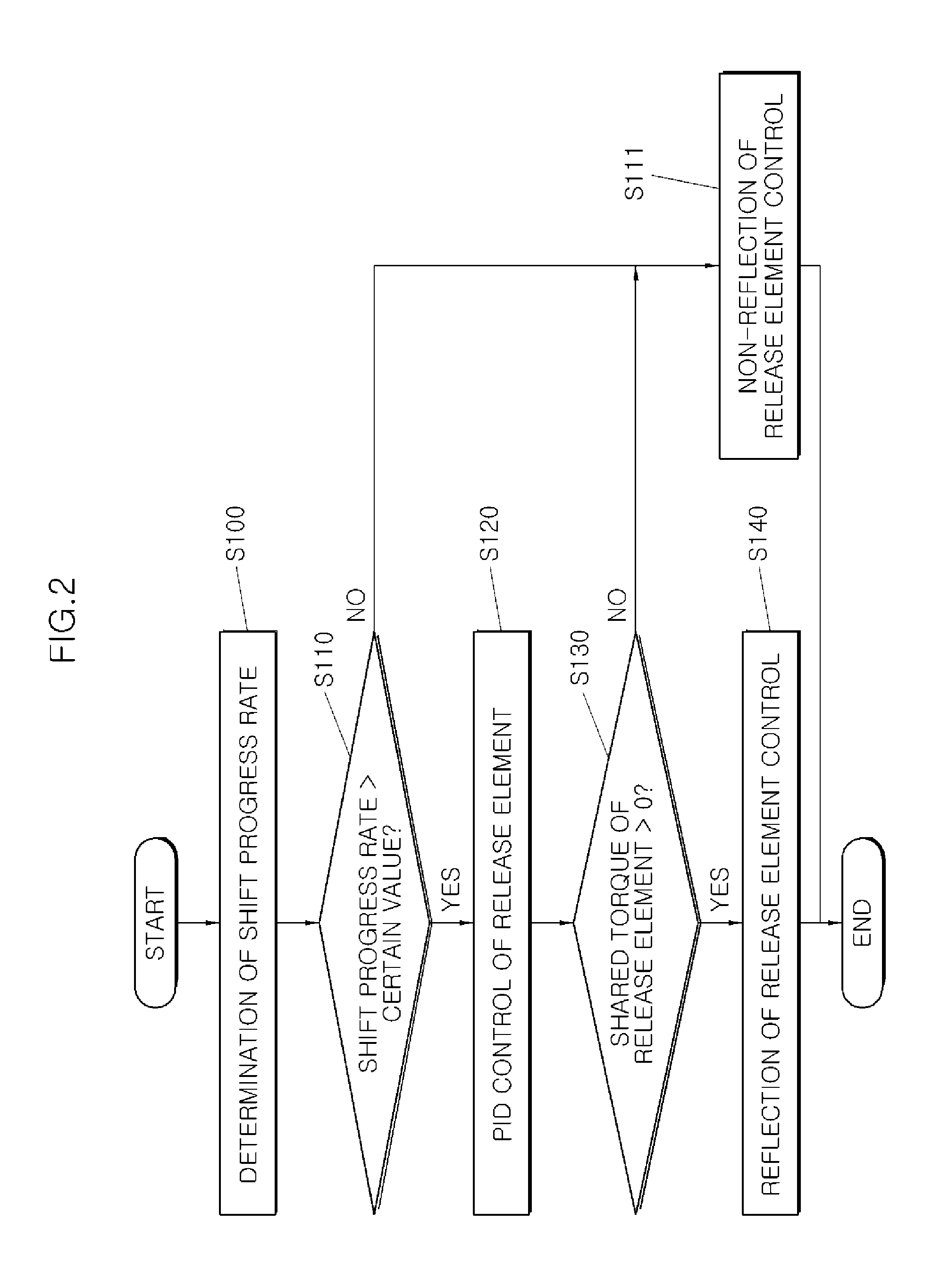
[0026]FIG. 2 is a flowchart illustrating a method of controlling an automatic transmission for reducing synchronization shock during an upshift in an accelerated state according to an exemplary embodiment of the present invention. FIG. 3 is a graph illustrating a process to which the method of controlling an automatic transmission...


PUM


Abstract

A method of controlling an automatic transmission for reducing synchronization shock during an upshift in an accelerated state may include determining a shift progress rate, performing shift progress rate determination of determining whether the determined shift progress rate is higher than a certain value, performing PID control of a release element when the shift progress rate is determined to be higher than the certain value, performing release element-shared torque determination of determining whether a shared torque of the release element is higher than 0, and reflecting the PID control in the release element when the shared torque of the release element is determined to be higher than 0.

Description

CROSS-REFERENCE TO RELATED APPLICATIONS[0001]The present application claims priority to Korean Patent Application No. 10-2014-0107270, filed on Aug. 18, 2014, which is incorporated herein by reference in its entirety.BACKGROUND OF THE INVENTION[0002]1. Field of the Invention[0003]Exemplary embodiments of the present invention relate to a method of controlling an automatic transmission for reducing synchronization shock during an upshift in an accelerated state; and, particularly, to a method of controlling an automatic transmission for reducing synchronization shock during an upshift in an accelerated state, capable of minimizing synchronization shock by a torque step generated after the end of an actual speed change range during an upshift in an accelerated state.[0004]2. Description of Related Art[0005]In general, a shift feeling during a power-on upshift (upshift generated in a case in which a vehicle is accelerated by pressing of an accelerator), which frequently occurs in an au...

Claims


Application Information

Patent Timeline
IPC IPC(8): F16H61/04
CPCF16H2061/0492F16H61/0403
Inventor LEE, CHAN-HOYANG, DONG-HOKIM, YOUNG-CHULKIM, SANG-JOONCHA, JUNG-MIN
Owner HYUNDAI MOTOR CO LTD
Learn More