Laser cutting machine for reflective strip production

A laser cutting machine and cutting device technology, applied in laser welding equipment, welding equipment, metal processing equipment, etc., can solve the problems of slow working speed, changing knife molds, unfavorable continuous production, etc., and achieve the effect of avoiding material indentation

Inactive Publication Date: 2014-03-26
FOSHAN KACHUN GARMENT
View PDF8 Cites 6 Cited by
  • Summary
  • Abstract
  • Description
  • Claims
  • Application Information

AI Technical Summary

Problems solved by technology

[0003] Traditional reflective materials with patterns have two production methods in engraving and cutting: 1. Rolling and cutting, that is, through the pressure of a steel knife or a mold, the pressure acts on the reflective material to press out a certain shape, and then remove excess waste through indentation , this process is generally completed by a die-cutting machine; the disadvantages of this production method: 1. Because the hardness of the reflective material is relatively high, the knife mold is easy to passivate; 2. The knife mold needs to be replaced frequently, and the cost is high; 3. Some It is difficult to express the pattern with a knife mold; 2. Cut the reflective material through the glass tube laser (the glass tube laser focuses and diffuses the laser beam through the optical lens, and the optical lens is mechanically moved to carry out optical transmission)
After the laser cuts a section of material, the pressure and friction of the pressure wheel are driven by the motor to transport the marked section of material, and then the next section is marked. Since the material is fixed, there is a certain distance between the front and back of the material. The working distance is limited, only suitable for products with relatively short processing patterns
[0004] Disadvantages: 1. Slow working speed; 2. The life of the laser is only about 1000 hours; 3. It is not conducive to continuous production

Method used


Image

  • Laser cutting machine for reflective strip production

Examples


Embodiment Construction

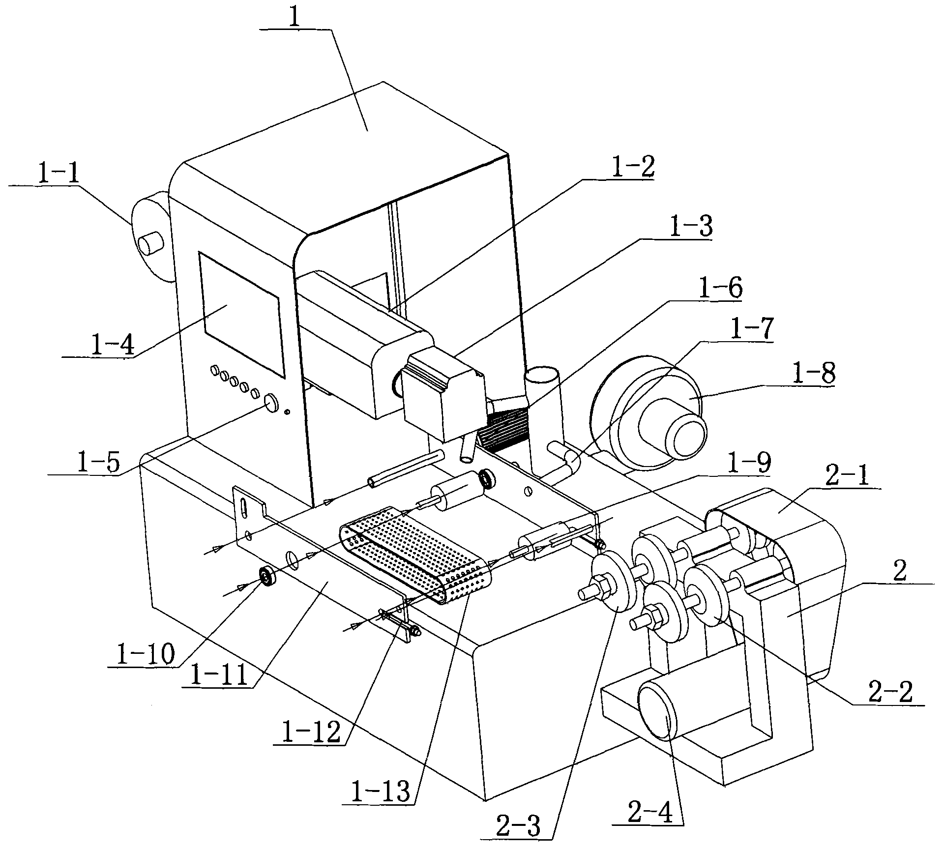
[0010] see figure 1 , the specific embodiment adopts the following technical scheme: it includes a cutting device 1 and a receiving and discharging waste device 2; the receiving and discharging waste device 2 is arranged on the right side of the cutting device 1, and the cutting device 1 includes a feeding device 1-1 , laser cooling device 1-2, metal tube laser transmitter 1-3, code calculator 1-4, emergency stop switch 1-5, synchronous motor 1-6, suction device 1-7, fan 1-8, transmission Drum 1-9, positioning wheel 1-10, fixed bracket 1-11, belt tension adjuster 1-12 and perforated belt 1-13, feeding device 1-1 is arranged on the upper part of the left side of cutting device 1, laser cooling device 1-2 is set on the right side of the feeding device 1-1, the metal tube laser emitter 1-3 is set on the right side of the laser cooling device 1-2, and the code calculator 1-4 is set on the left side of the front part of the cutting device 1 On the upper end, the emergency stop swi...


PUM


Abstract

The invention relates to a cutting machine, in particular to a laser cutting machine for reflective strip production. A feeding device (1-1) is arranged on the upper portion the left side of a cutting device (1). A laser cooling device (1-2) is arranged on the right side of the feeding device (1-1). A metal tube laser emitter (1-3) is arranged on the right side of the laser cooling device (1-2). An air suction device (1-7) is arranged on the right side of a synchronous motor (1-6). A draught fan (1-8) is arranged on the rear side of the air suction device (1-7). A hole belt (1-13) is arranged below the metal tube laser emitter (1-3). The air suction device (1-7) is arranged on the lower portion of the hole belt (1-13). A belt tightness degree regulator (1-12) is arranged at the right end of a fixed support (1-11). According to the laser cutting machine for reflective strip production, a metal tube laser device is used for replacing a traditional glass tube laser device, a coder achieves synchronization of production numerical control, conveyance and cutting, and generation of material indentations is avoided due to the arrangement of the air suction device.

Description

Technical field: [0001] The invention relates to a cutting machine, in particular to a laser cutting machine for producing reflective materials. Background technique: [0002] The laser of the traditional laser cutting machine is a glass tube laser, and the traditional operation mode is: static marking and cutting, not a motion mode, that is, the material needs to stop on the conveyor belt during marking, marking and then cutting, and then conveyed away. The static principle is that a pressure wheel is pressed on the material. After the laser cuts a section of material, the pressure and friction of the pressure wheel are driven by the motor to transport the marked material, and then the next section is marked. This method, sometimes Because the pressure of the pressure roller crushes the material, and the speed is slow. [0003] Traditional reflective materials with patterns have two production methods in engraving and cutting: 1. Rolling and cutting, that is, through the p...

Claims


Application Information

Patent Timeline
Patent Type & Authority Applications(China)
IPC IPC(8): B23K26/38B23K26/70
CPCB23K26/38B23K26/0838B23K26/16B23K26/702B23K26/703
Inventor 欧展荣
Owner FOSHAN KACHUN GARMENT
Why Eureka
Try Eureka