Osteosynthesis device

a technology of osteosynthesis and marrow, which is applied in the field of osteosynthesis devices, can solve the problems of affecting the marrow nails loosening with the elapse of time, and the patient to feel extreme discomfort, so as to improve the reliability of fixation of fractured portions, improve the degree of freedom, and improve the reliability of fixing the fractured parts

Inactive Publication Date: 2016-02-25
KURUME UNIVERSITY +1
View PDF31 Cites 24 Cited by
  • Summary
  • Abstract
  • Description
  • Claims
  • Application Information

AI Technical Summary

Benefits of technology

[0045]The osteosynthesis device according to the present invention has circular holes, base portion side holes, and tip portion side holes of a plurality of directions and different angles provided in the intramedullary nail and therefore is increased in the options of the insertion position or insertion direction of a fixing pin or screw despite being a single device, is thus capable of accommodating various modes of operation by the operator in accordance with the circumstances of fractured portions, and is improved in reliability of fixation of the fractured portions.
[0046]With the osteosynthesis device having the long hole or hole with the major axis and opening long in the same direction as the length direction of the intramedullary nail, the hole enables the insertion angle to be set arbitrarily and therefore the device, despite being a single device, is high in the degree of freedom of the insertion position or insertion direction of a fixing pin or screw, is thus capable of accommodating various modes of operation by the operator in accordance with the circumstances of fractured portions, and is improved in reliability of fixation of the fractured portions.
[0047]Further, with the osteosynthesis device having the end plate mounted on the outer surface of the elbow side of the ulna and where the end plate has the penetrating hole, through which is inserted the threaded screw that is inserted and screwed on from the base end of the intramedullary nail and along the length direction of the intramedullary nail, and the threaded screw is inserted and screwed on through the end plate, the operator who has selected the use of the intramedullary nail and the end plate can put the end plate in contact with the outer surface of the elbow side of the ulna and screw the end plate onto the intramedullary nail by means of the threaded screw inserted through the penetrating hole.
[0048]With the osteosynthesis device having the endplate mounted on the outer surface of the elbow side of the ulna and the threaded screw by which the end plate is screwed onto the threaded hole in the base end surface of the intramedullary nail and where the end plate has the base plate with one or more penetrating holes formed in the thickness direction and the plurality of projections projecting from the base plate toward the ulna side and contacting the outer surface of the olecranon side of the ulna, the surface of the base plate at the side opposite the ulna is formed to have no projections or to be smooth, one of either or both of the base plate and the projections of the end plate has or have flexibility or elasticity, the end plate is arranged to press the olecranon toward the tip portion side of the ulna by means of the elastic force of the base plate or the projections, and the threaded screw is used by being inserted in any on

Problems solved by technology

For example, with the plate fixation method, a metal plate is set along a wide range of an elbow portion, causing a patient to feel extreme discomfort.
Also with the tension band wiring method, there has occurred a problem where despite the nails inserted into the marrow being fastened and fixed by the wi

Method used


Image

  • Osteosynthesis device
  • Osteosynthesis device
  • Osteosynthesis device

Examples


Embodiment Construction

[0073]Embodiments of the present invention shall now be described in detail based on FIG. 1 to FIG. 10.

[0074](Osteosynthesis Device D1)

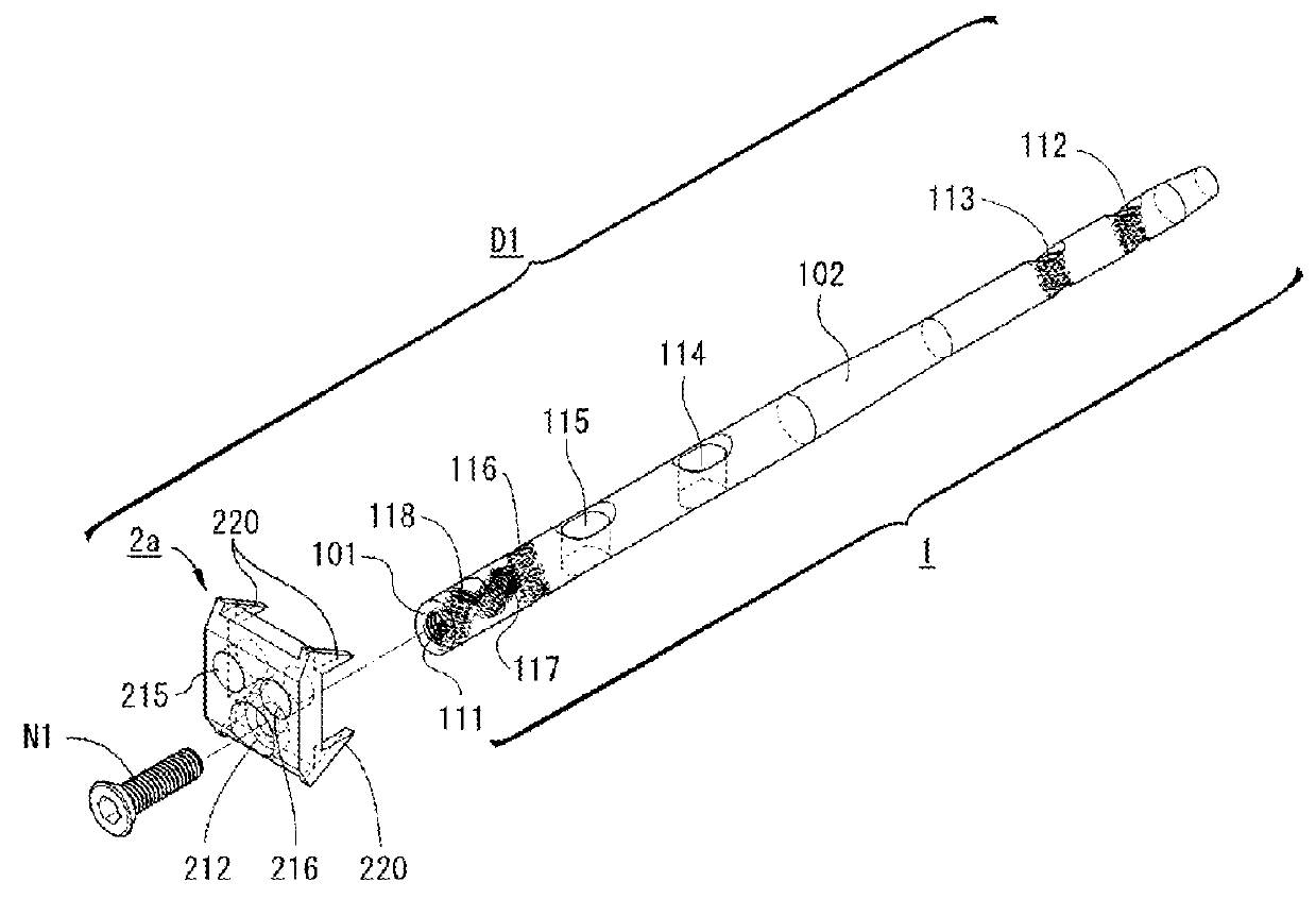
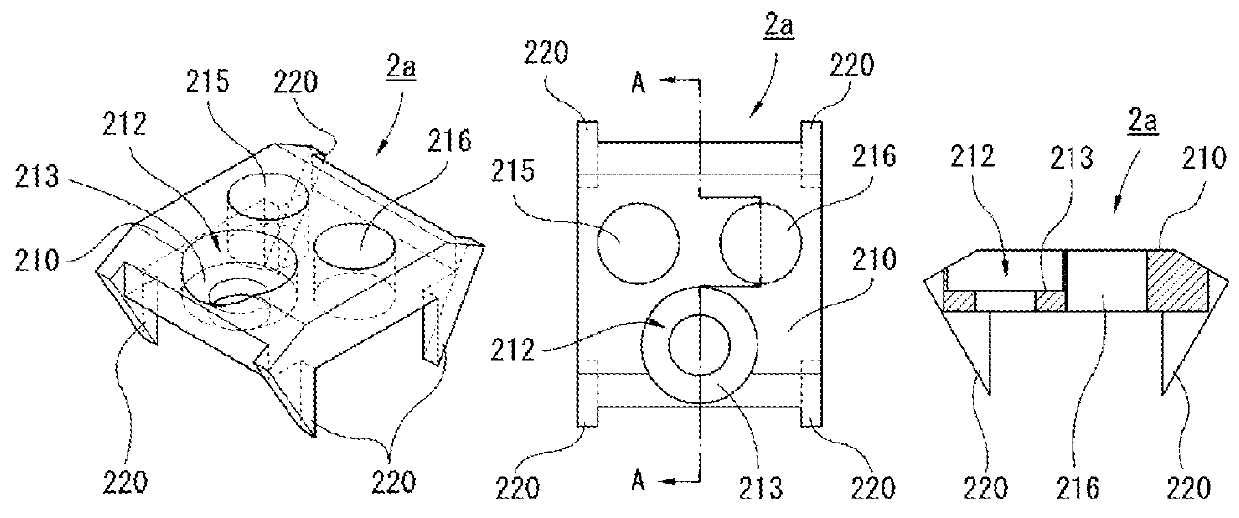
[0075]An osteosynthesis device D1 is a device used, in case of fracture of an olecranon side of an ulna 3, to fix and reposition respective bone fragments. The osteosynthesis device D1 includes an intramedullary nail 1 inserted into the ulna 3, an end plate 2a mounted on an outer surface of the ulna 3 at the olecranon 31 side, and a single threaded screw N1 arranged to screw on the end plate 2a to the intramedullary nail 1 (see FIG. 1).

[0076]Screws S are used in combination with the osteosynthesis device D1 as fixing members for fixing, etc., the inserted intramedullary nail 1 onto the ulna 3. Each screw S is an acute threaded screw having rigidity enabling screwing into a bone and has a (headless) structure without a head portion at a base end (see FIG. 6 and FIG. 7). In the present embodiment, a titanium alloy is used as the material that forms the...


PUM


Abstract

An osteosynthesis device is provided, which, while being a single device, is wide in a range of fixing positions or fixing methods that can be selected in a repositioning operation, enables firm fixation of an affected portion, and alleviates feeling of discomfort felt at the affected portion after the operation.
An osteosynthesis device D1 is a device used, in case of fracture of an olecranon side of an ulna, to fix and reposition respective bone fragments and includes an intramedullary nail 1 inserted into the ulna 3, an end plate 2a mounted on an outer surface of the ulna at the olecranon 31 side, and a threaded screw N1 arranged to screw on the end plate to the intramedullary nail. Screws S are used in combination with the osteosynthesis device D1 to fix, etc., the inserted intramedullary nail 1 onto the ulna 3. The intramedullary nail 1, which is a round rod body having a tapering tip end portion and has a thickness enabling entry into the marrow of the ulna and a predetermined length, includes a threaded hole 111 formed in a base end surface 101, long holes 114 and 115 formed at a base end side with respect to a central portion of a circumferential surface 102, and circular holes 112, 113, 116, 117, and 118 formed at predetermined parts between a tip portion side and the base end side of the circumferential surface 102.

Description

CROSS REFERENCE TO RELATED APPLICATIONS[0001]This patent application is a U.S. national stage application under 35 U.S.C. §371 of International Patent Application No. PCT / JP2014 / 060328 filed on Apr. 9, 2014, which claims the benefit of foreign priority to Japanese Patent Application No. JP 2013-082661 filed on Apr. 11, 2013. The International application was published in Japanese on Oct. 16, 2014, as International Publication No. WO 2014 / 168184 A1 under PCT Article 21(2).TECHNICAL FIELD[0002]The present invention relates to an osteosynthesis device. More specifically, it relates to an osteosynthesis device used, in case of fracture of an olecranon side of an ulna, to fix and reposition respective bone portions to the original bone shape.BACKGROUND ART [0003]There is a surprisingly high number of cases of fracture of an olecranon side of an ulna and although for treatment thereof, there are the so-called “plate fixation method (an operation method using a curved plate and fixing thre...

Claims


Application Information

Patent Timeline
IPC IPC(8): A61B17/72A61B17/80
CPCA61B17/809A61B17/7225
Inventor NAKAMURA, HIDETOMOFUKUTOYO, RYUTA
Owner KURUME UNIVERSITY
Why Eureka
Try Eureka