
Apparatus and methods for securing elastic to a carrier web

a carrier web and elastic technology, applied in the field of apparatus and methods for securing elastic to a carrier web, can solve the problems of wasting material resources, reducing the service life of the product, so as to achieve the effect of reducing the amount of adhesive bonding

Active Publication Date: 2016-03-03
CURT G JOA
View PDF4 Cites 71 Cited by
  • Summary
  • Abstract
  • Description
  • Claims
  • Application Information

AI Technical Summary

Benefits of technology

The present invention provides a method for making a nonwoven elastic laminate by applying elastic strands or filaments to a base nonwoven layer, and optionally shaping the elastics into a meandering pattern between bond points of the nonwoven layers. The elastics can be bonded to the nonwoven layer with adhesive or other means, or they can be separated from one another through ultrasonic force or electrostatic separation and captured within the nonwoven layers. This method allows for the creation of a laminate with elastics maintained in a relatively unelongated state, minimizing adhesive bonding and allowing for flexibility in the elastics' position within the nonwoven layers. The elastics can also be shaped into different patterns to create a more complex bonding pattern, further enhancing the elastics' retention within the nonwoven layers.

Problems solved by technology

Not all machine configurations can be adapted from a full length poly chassis to a poly insert configuration due to space and / or cost restrictions.
This is a waste of the material resource and adds additional cost to the product.
However, typical slip / cut application of poly patch to a continuous web does not work well because of the elasticity of the poly web.
This can result in a short patch-long patch output from the slip / cut where one or more of the resulting poly catches are extremely distorted on the carrier web.
At this level of elongation, there is a lot of stress on the elastic and the elastic has an increased likelihood of breaking, which can lead to machine downtime.

Method used


Image

  • Apparatus and methods for securing elastic to a carrier web
  • Apparatus and methods for securing elastic to a carrier web
  • Apparatus and methods for securing elastic to a carrier web

Examples


Embodiment Construction

[0037]Although the disclosure hereof is detailed and exact to enable those skilled in the art to practice the invention, the physical embodiments herein disclosed merely exemplify the invention which may be embodied in other specific structures. While the preferred embodiment has been described, the details may be changed without departing from the invention.

[0038]It is noted that the present techniques and apparatus are described herein with respect to products such as diapers, but as previously mentioned, can be applied to a wide variety of processes in which discrete components are applied sequentially.

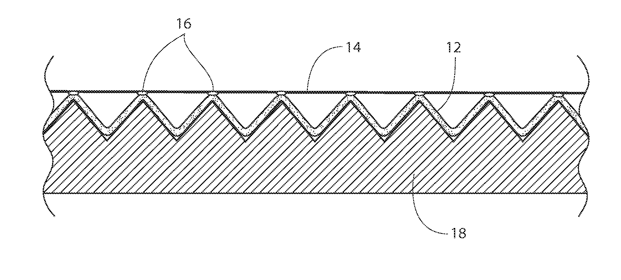
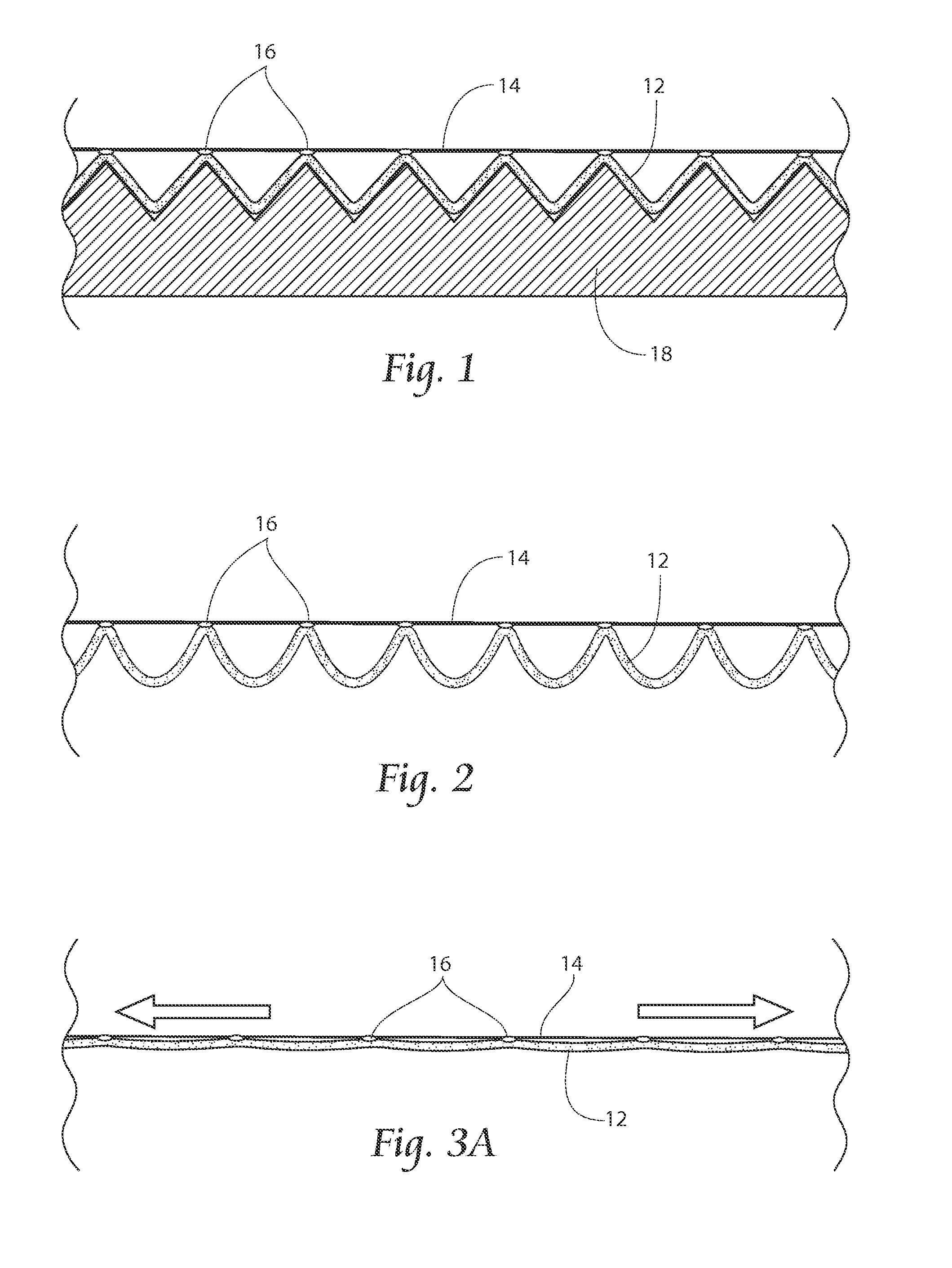
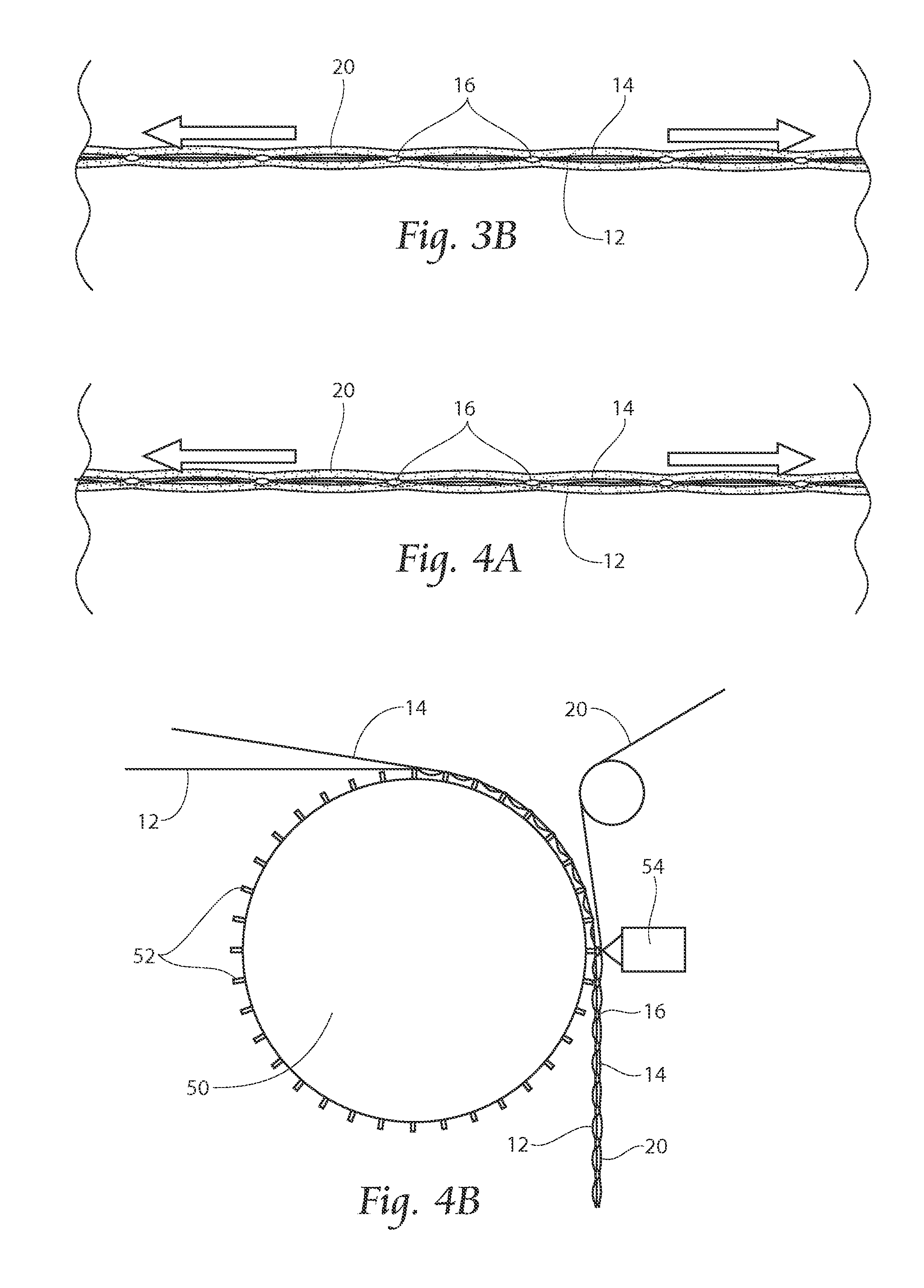
[0039]Referring now to FIG. 1, a side view of an apparatus and method of forming an elastic laminate is shown. A base support structure 18 is provided with peaks and valleys, which can be a “V” shape. A preferably non-woven layer 12 is laid into the valleys. Atop the nonwoven 12 is laid an unstretched or relatively unstretched elastic layer 14, which can comprise strands or a web o...


PUM

PropertyMeasurementUnit
movementaaaaaaaaaa
elasticaaaaaaaaaa
distancesaaaaaaaaaa

Abstract

Apparatus and methods are provided to allow for creation an elastic laminate. Non-stretched elastic can be laid at peaks over a nonwoven layer contained in valleys and atop peaks. Stretched elastic can be laid over tented nonwoven to create nonwoven tunnels when a second nonwoven is laid atop the first nonwoven and elastic, and the tunnels resist un-stretching of stretched elastic strands by frictional or obstruction forces. A laminated material comprising a first and second layer of material bonded at spaced apart bond sites is disclosed, with a plurality of elastic strands disposed in a non-linear manner between said first and second layer of material, so that said strands meander in a cross-machine direction and traverse a machine direction line, restraining movement of the strands by frictional forces between the strands and the non-woven layers.

Description

RELATED APPLICATION[0001]This application claims the benefit of co-pending U.S. Provisional Patent Application Ser. No. 62 / 041,876, filed 26 Aug. 2014.BACKGROUND OF THE INVENTION[0002]This invention relates to an apparatus and method for producing a laminate of elastic material by attaching a non-elongated elastic to a carrier web or webs. While the description provided relates to diaper manufacturing, the apparatus and methods are easily adaptable to other applications.[0003]Generally, diapers comprise an absorbent insert or patch and a chassis, which, when the diaper is worn, supports the insert proximate a wearer's body. Additionally, diapers may include other various patches, such as tape tab patches, reusable fasteners and the like. The raw materials used in forming a representative insert are typically cellulose pulp, tissue paper, poly, nonwoven web, acquisition, and elastic, although application specific materials are sometimes utilized. Usually, most of the insert raw mater...

Claims


Application Information

Patent Timeline
Patent Type & Authority Applications(United States)
IPC IPC(8): A61F13/15A61F13/49
CPCA61F13/15593A61F13/49011A61F13/4902A61F13/49017A61F13/49014A61F13/49009B29K2995/0046B29L2031/4878B29C65/086B29C66/1122B29C66/21B29C66/221B29C66/234B29C66/433B29C66/7294B29C66/81429B29C66/81431B29C66/81433B29C66/81465B29C66/83411B29C66/83415B29C66/83511
Inventor HOHM, GOTTFRIED, JASONWEI, WEIBOWE, DEBRA, HEUSMIDDLESWORTH, JEFF
Owner CURT G JOA
Learn More