Sheet post-processing device and image forming device

a post-processing device and image forming technology, applied in the direction of electrographic process equipment, thin material processing, instruments, etc., can solve the problems of increasing the cost of components, the inability to cleanly push out the front tray, and the rotation of the long sheet stack, so as to achieve stably push and not increase the length of the push-out member

Active Publication Date: 2016-03-03
KONICA MINOLTA INC
View PDF2 Cites 1 Cited by
  • Summary
  • Abstract
  • Description
  • Claims
  • Application Information

AI Technical Summary

Benefits of technology

[0010]The present invention was achieved in view of the problems described above, and aims to provide a sheet post-processing device and an image forming device that can stably push out the long sheet stack without increasing length of the push-out member.

Problems solved by technology

However, in a case in which an image forming device forms images by using recording sheets of various sizes, when a push-out member that is short in FD length is used to push a recording sheet stack that is long in FD length (hereafter, a “long sheet stack”) to the front tray, it can occur that the long sheet stack rotates and cannot be cleanly pushed out to the front tray.
If the push-out member is made longer in response to such a problem, a high mechanical strength becomes required for the push-out member, leading to an increase in component cost.
Further, an image forming device directed to space saving usually does not have much leeway in terms of space, and therefore location of the push-out member is limited and increasing length of the push-out member may not be possible.
Further, in order to drive a long push-out member a powerful drive source is required, but such a drive source has a problem of high power consumption.
When a long push-out member is used, power consumption is also high when a recording sheet stack having a short length is pushed out, consuming unnecessary power in a way that is contrary to power saving requirements.

Method used


Image

  • Sheet post-processing device and image forming device
  • Sheet post-processing device and image forming device
  • Sheet post-processing device and image forming device

Examples


Embodiment Construction

[0030]The following describes, with reference to the drawings, a sheet post-processing device and an image forming device according to embodiments of the present invention.

(1) Configuration of Image Forming Device

[0031]First, a configuration of an image forming device pertaining to the present embodiment is described below.

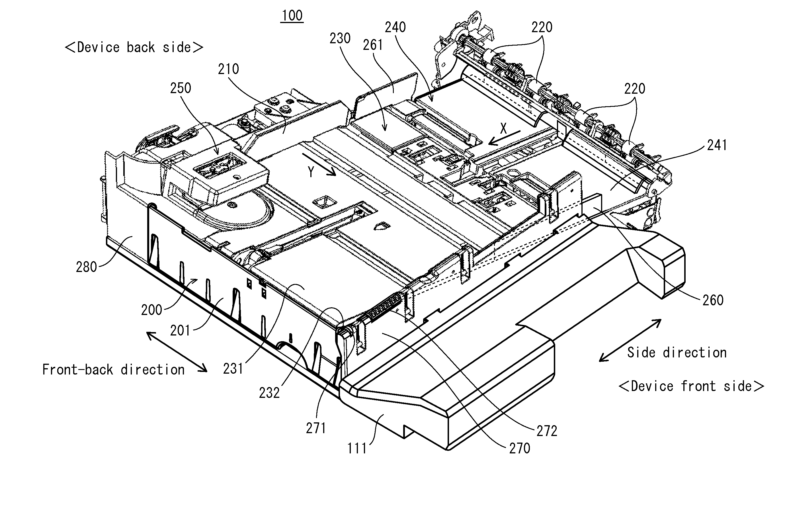
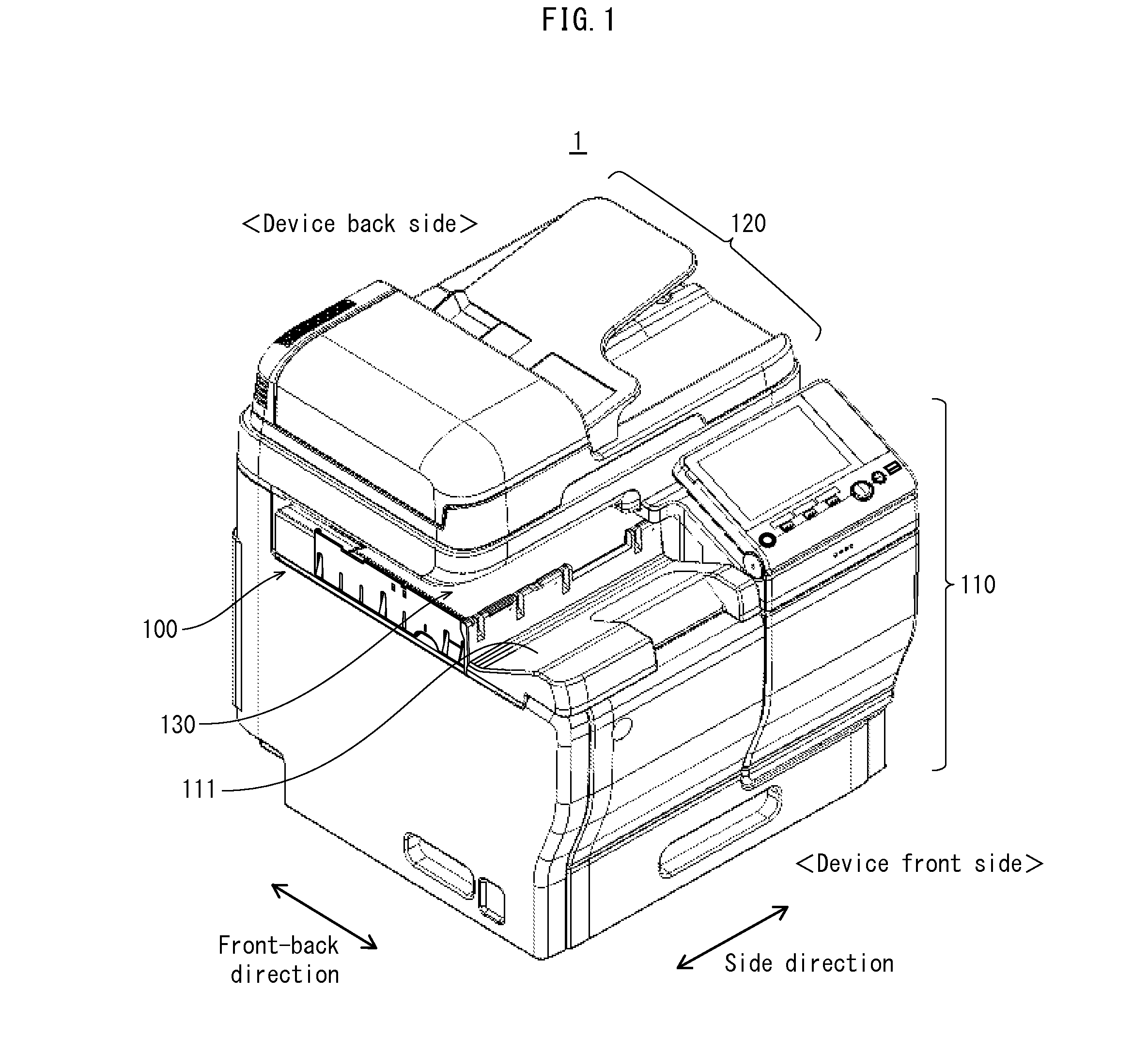
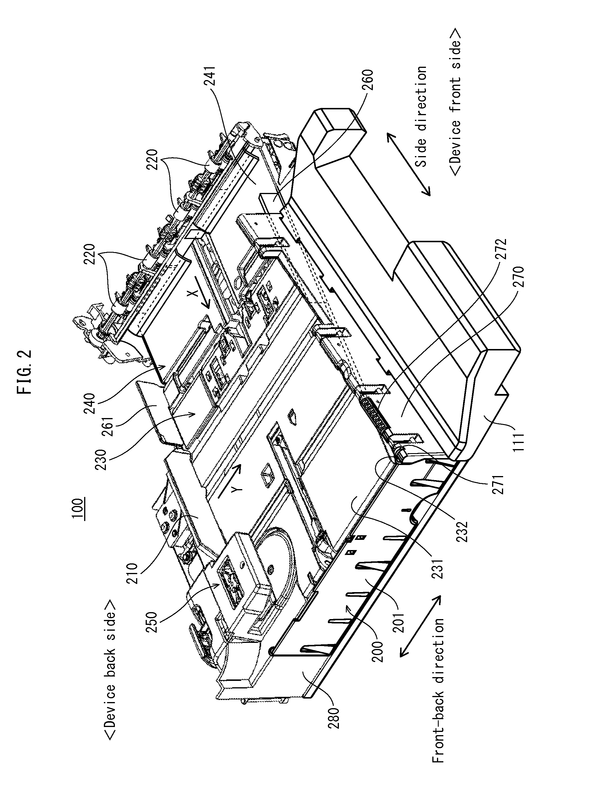
[0032]FIG. 1 is a perspective view illustrating major components of an image forming device pertaining to the present embodiment. As illustrated in FIG. 1, an image forming device 1 includes a sheet post-processing device 100, a printer 110, and a scanner 120. The scanner 120 reads a document and generates image data. The printer 110 forms an image on a recording sheet, based on one of image data generated by the scanner 120 and image data received from another device.

[0033]The image forming device 1 is an in-body paper ejection type and is provided with an in-body space 130 between the sheet post-processing device 100 and the scanner 120 for ejection of the recor...


PUM


Abstract

A sheet post-processing device for post-processing of a recording sheet ejected from an image forming device in an ejection direction, the sheet post-processing device including: a first tray on which the recording sheet is placed after ejection; a push-out member that pushes out, in a push-out direction different from the ejection direction, the recording sheet placed on the first tray; and a guide member adjacent to an ejection direction downstream end of the first tray, the guide member supporting a portion of the recording sheet that protrudes from the first tray in the ejection direction. The guide member includes a resistive force reduction unit that reduces a resistive force that occurs due to contact between the guide member and the recording sheet, the resistive force hindering the pushing out of the recording sheet when the push-out member pushes out the recording sheet.

Description

CROSS-REFERENCE TO RELATED APPLICATION[0001]The present invention claims priority under 35 U.S.C. §119 to Japanese Application No. 2014-178972, filed Sep. 3, 2014, the entire content of which is incorporated herein by reference.BACKGROUND OF THE INVENTION[0002]1. Field of the Invention[0003]The present invention relates to sheet post-processing devices and image forming devices, and specifically to techniques for stably ejecting a sheet that is long in a feed direction (FD).[0004]2. Related Art[0005]Among image forming devices such as photocopiers are in-body paper ejection types in which a printer is disposed in a space (hereafter, “in-body space”) below a scanner and a recording sheet on which an image is formed by the printer is temporarily ejected into the in-body space.[0006]Among in-body paper ejection types of image forming devices, a configuration may be considered in which recording sheets ejected into the in-body space are stacked into a recording sheet stack and pushed to...

Claims


Application Information

Patent Timeline
Patent Type & Authority Applications(United States)
IPC IPC(8): G03G15/00
CPCG03G15/6573G03G15/6582B65H31/20B65H31/3054B65H2404/1312B65H2405/11151B65H2405/1118B65H2405/141B65H2405/1412G03G2215/00421
Inventor TAKATSU, HIROAKINAKAYAMA, NAOYAEGUCHI, TATSUYA
Owner KONICA MINOLTA INC
Why Eureka
Try Eureka