
Self-rectifying rram cell structure and rram 3D crossbar array architecture

Active Publication Date: 2016-03-03
WINBOND ELECTRONICS CORP
View PDF4 Cites 17 Cited by
  • Summary
  • Abstract
  • Description
  • Claims
  • Application Information

AI Technical Summary

Benefits of technology

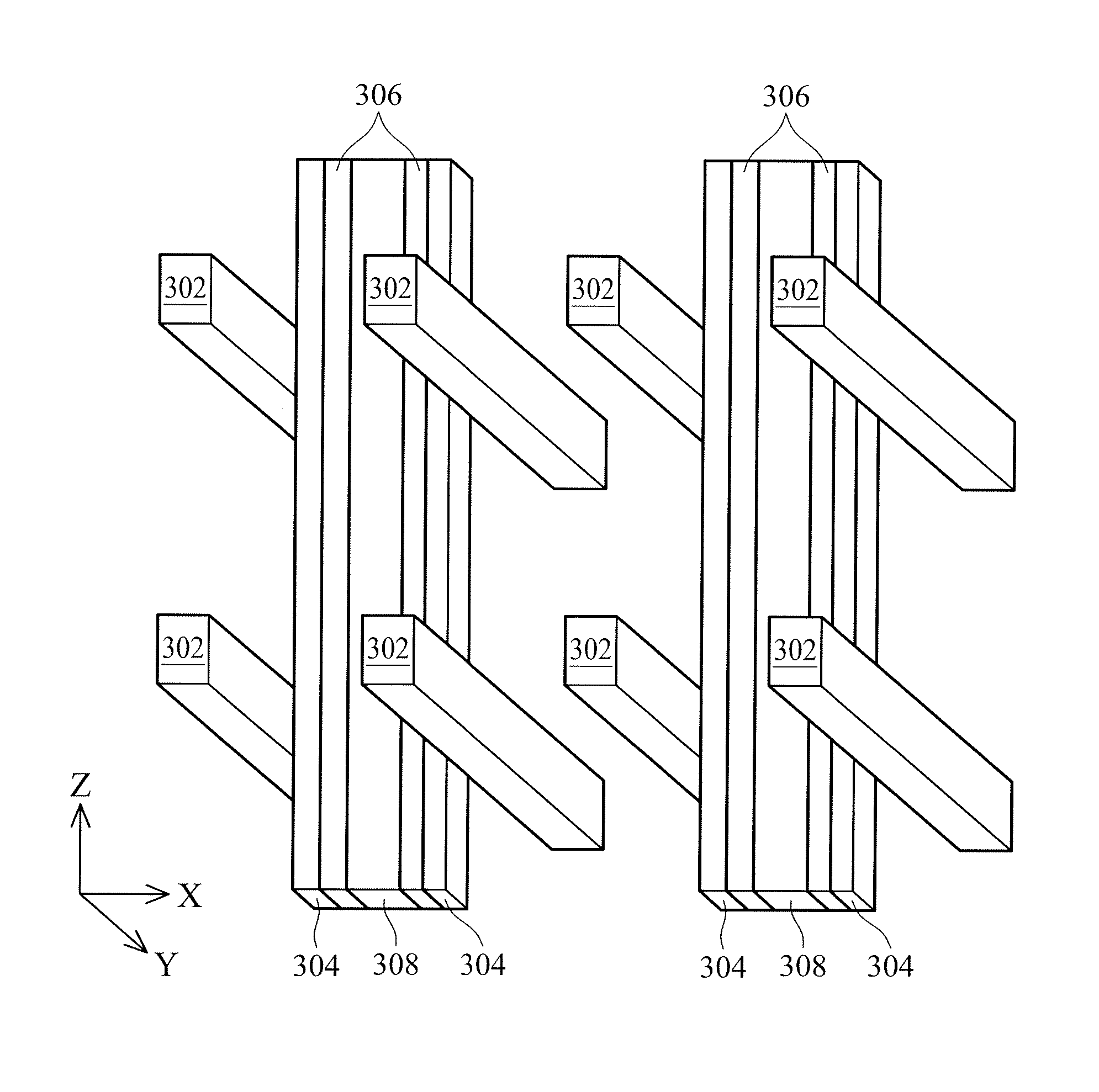
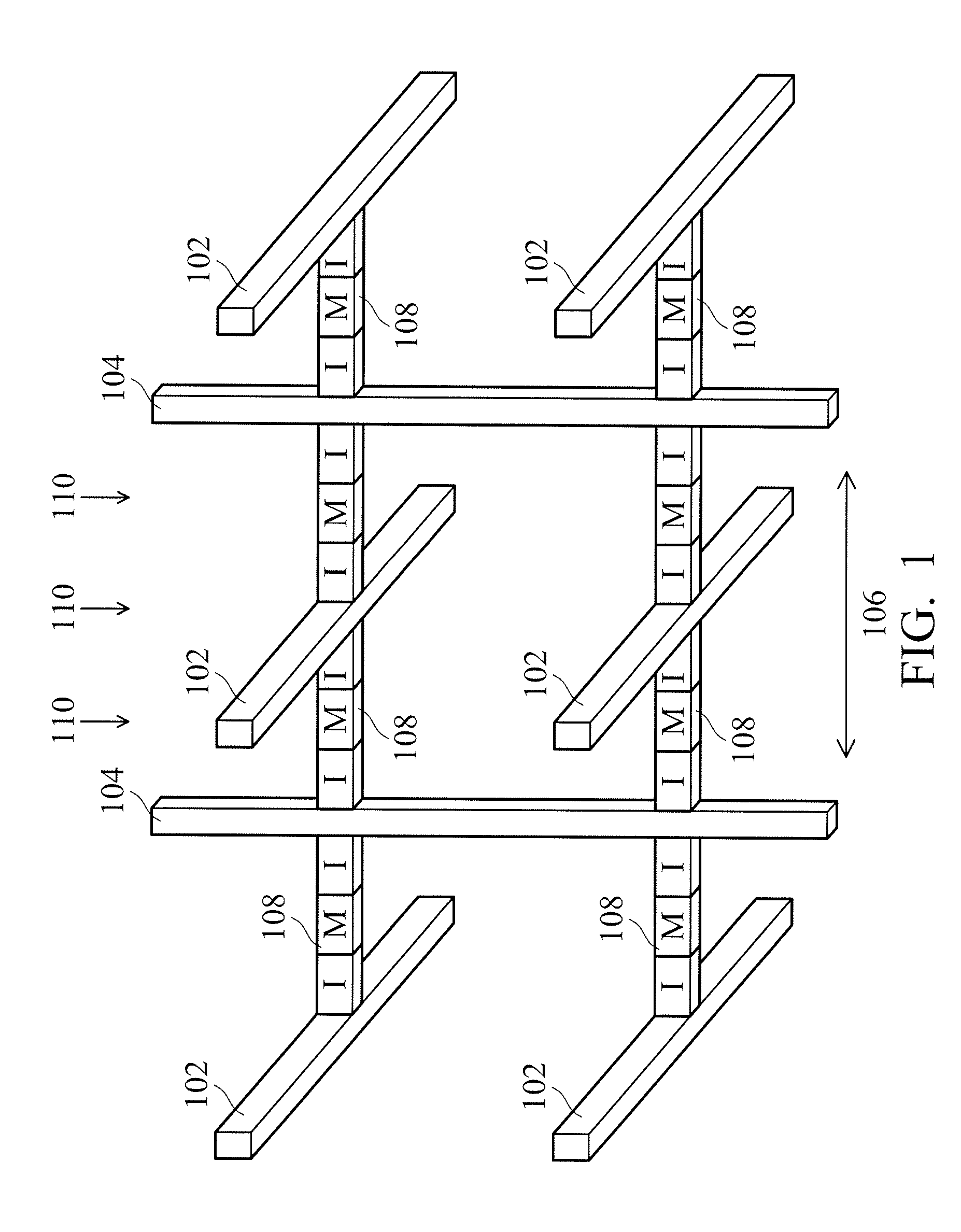
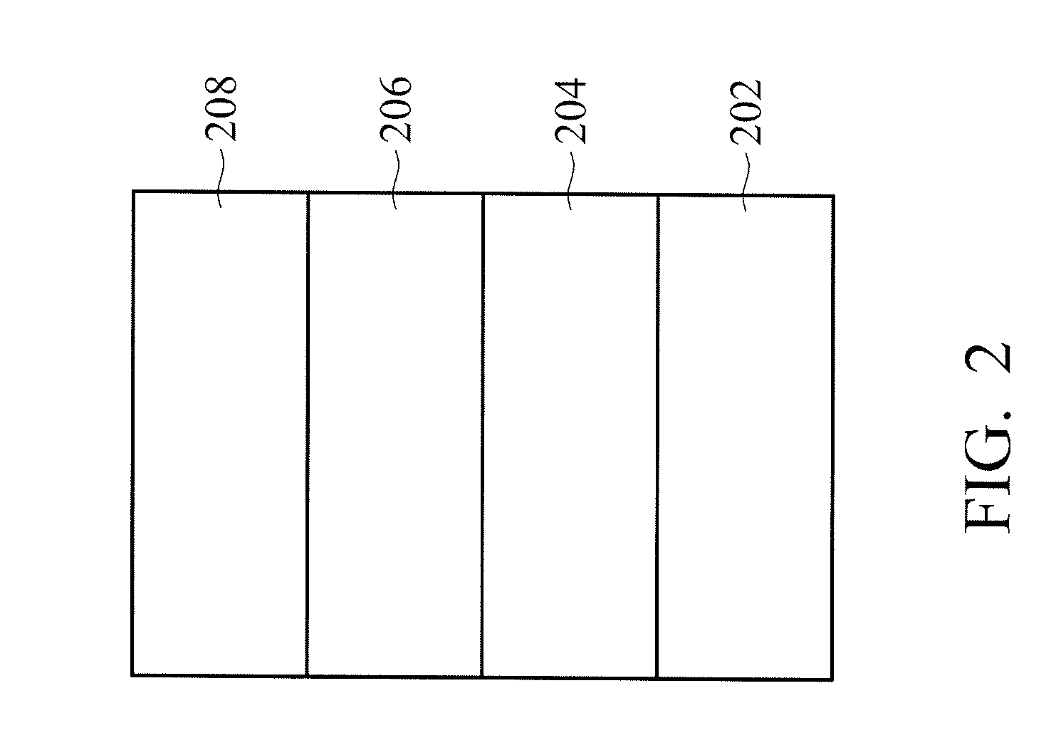
The patent text describes new structures for RRAM (resistive random access memory) cells and a 3D crossbar array architecture for them. The cells include a first electrode layer, a second electrode layer, and a first resistive switching layer, which is sandwiched between the first electrode layer and the second electrode layer. The first resistive switching layer has a lower bandgap than the second resistive switching layer. The 3D crossbar array architecture includes horizontal and vertical conductive lines with the first and second resistive switching layers formed on the sidewalls of the conductive lines and in contact with the vertical lines. The first resistive switching layer has a lower bandgap than the second resistive switching layer. These structures provide improved performance and reliability of RRAM cells.

Problems solved by technology

However, it has been found that further miniaturization of flash memory is limited due to the increasing cost.
Although the RRAM crossbar array architecture is simple, there are still many problems that need to be overcome for fabrication, especially for three-dimensional (3D) crossbar array architectures.
Without a vertical 3D architecture, the RRAM will most likely not be able to compete with 3D NAND memories in terms of bit cost for mass data storage.
However, in the 1R structure (having a resistive element only), undesired sneak current that flows through neighboring unselected memory cells significantly deteriorates the read margin, and limits the maximum size of the crossbar array to below 64 bits.
Among the memory cell structures, the 1T1R and 1BJT1R memory cell structures are undesirable because of the complicated and high-temperature fabrication requirements of MOSFETs and BJTs, while the complementary resistive switching (CRS) memory cell structure suffers from the issue of destructive read.
However, the 3D crossbar array architectures of the 1D1R or 1S1R memory cell structures still cannot be successfully fabricated.

Method used


Image

  • Self-rectifying rram cell structure and rram 3D crossbar array architecture
  • Self-rectifying rram cell structure and rram 3D crossbar array architecture
  • Self-rectifying rram cell structure and rram 3D crossbar array architecture

Examples


Embodiment Construction

[0020]The following description is of the best-contemplated mode of carrying out the disclosure. This description is made for the purpose of illustrating the general principles of the disclosure and should not be taken in a limiting sense. These are, of course, merely examples and are not intended to be limited. For example, the formation of a first feature over, above, below, or on a second feature in the description that follows may include embodiments in which the first and second features are formed in direct contact, and may also include embodiments in which additional features may be formed between the first and second features, such that the first and second features may not be in direct contact. In addition, the disclosure may repeat reference numerals and / or letters in the various examples. This repetition is for the purpose of simplicity and clarity and does not in itself dictate a relationship between the various embodiments and / or configurations discussed.

[0021]The discl...


PUM


Abstract

The present disclosure provides a self-rectifying RRAM cell structure including a first electrode layer formed of a nitride of a first metal element, a second electrode layer formed of a second metal element that is different from the first metal element, a first resistive switching layer and a second resistive switching layer. The first resistive switching layer is sandwiched between the first electrode layer and the second resistive switching layer, and the second resistive switching layer is sandwiched between the first resistive switching layer and the second electrode layer. The first resistive switching layer has a first bandgap that is lower than the second bandgap of the second resistive switching layer. Furthermore, a RRAM 3D crossbar array architecture is also provided.

Description

CROSS REFERENCE TO RELATED APPLICATIONS[0001]This application claims the benefit of Taiwan Patent Application No. 103129478 filed on August 27, 2014, entitled “SELF-RECTIFYING RRAM CELL STRUCTURE AND RRAM 3D CROSSBAR ARRAY ARCHITECTURE” which is hereby incorporated herein by reference.BACKGROUND[0002]1. Field of the Disclosure[0003]The present disclosure relates to a memory device, and in particular, it relates to a resistive random access memory (RRAM) cell structure and a 3D crossbar array thereof.[0004]2. Description of the Related Art[0005]As the functionality of integrated chips increases, the need for more memory also increases. Designers have been looking to decrease the size of the memory element and stack more memory elements in a unit area to achieve greater capacity and lower costs per bit. In the past few decades, the aggressive shrinkage of memory elements is due to advancements in lithography techniques. Flash memory has been widely used as large-capacity, inexpensive ...

Claims


Application Information

Patent Timeline
IPC IPC(8): H01L27/24H01L45/00
CPCH01L27/2481H01L45/1233H01L45/1253H01L45/146H10B63/84H10N70/841H10N70/20H10N70/8833H10N70/826
Inventor HOU, TUO-HUNGHSU, CHUNG-WEICHOU, CHUN-TSELAI, WEI-LI
Owner WINBOND ELECTRONICS CORP
Learn More