Large current female connector for high-speed transmission

Active Publication Date: 2016-03-03
BIZCONN INT CORP (SHEN ZHEN)
View PDF14 Cites 6 Cited by
  • Summary
  • Abstract
  • Description
  • Claims
  • Application Information

AI Technical Summary

Benefits of technology

[0018]In the present invention, the connector has a structure in which a power terminal in the upper terminal group and a corresponding power terminal in the lower terminal group are connected to form a big power terminal, and an insulating body trench for accommodating the big power terminal is disposed on the insulating body. One power terminal can carry only a limited amount of current, while a grand terminal combining two power terminals can carry much more current. Therefore, as a power terminal in

Problems solved by technology

With the popularity of the large-screen mobile terminal, the accompanying high power consumption has become an urgent issue that people have to address.
To solve this problem, high-capacity batteries are developed, but the charging current for a high-capacity battery is limited by the USB connector.
The dimens

Method used


Image

  • Large current female connector for high-speed transmission
  • Large current female connector for high-speed transmission
  • Large current female connector for high-speed transmission

Examples


Example

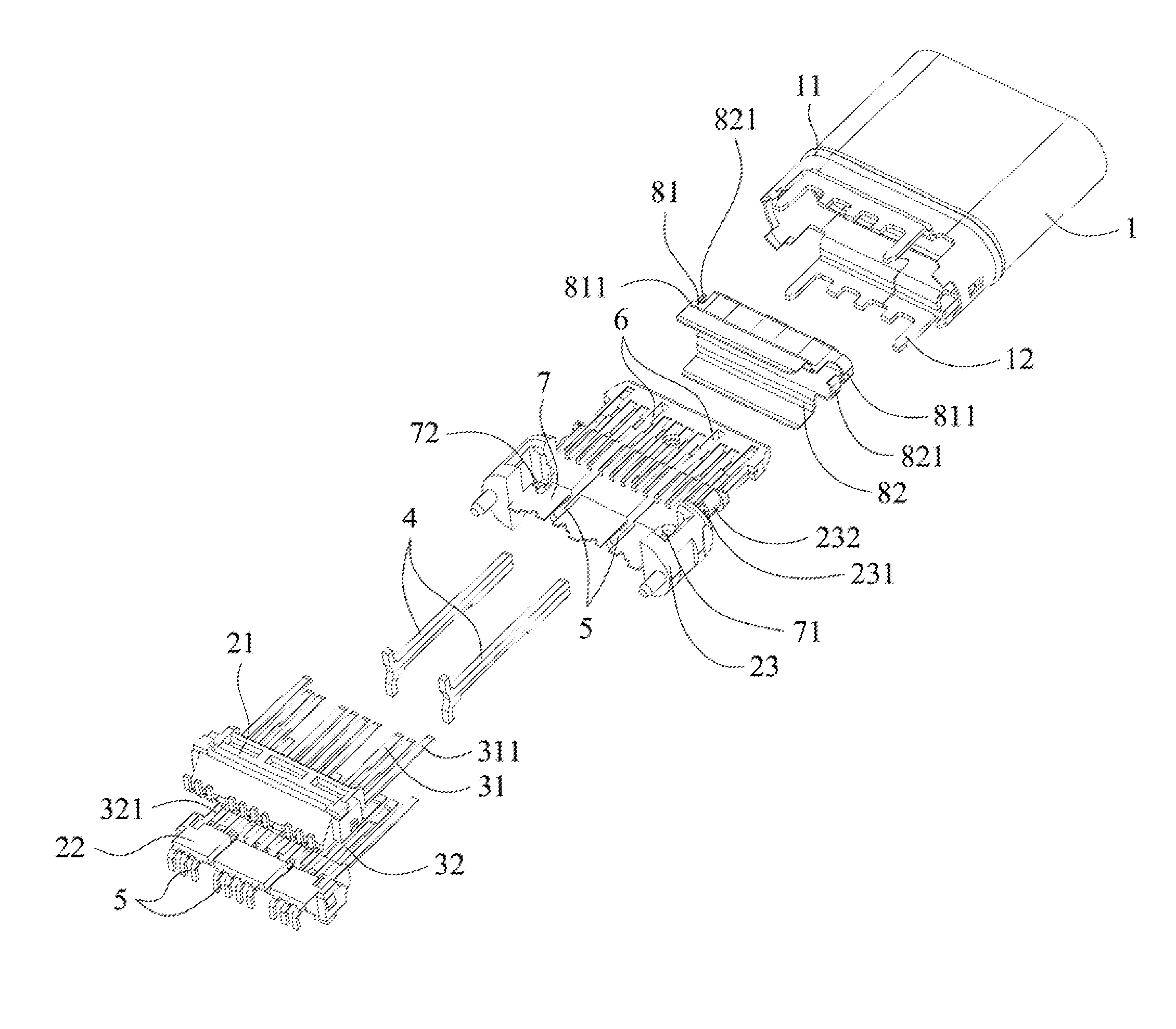
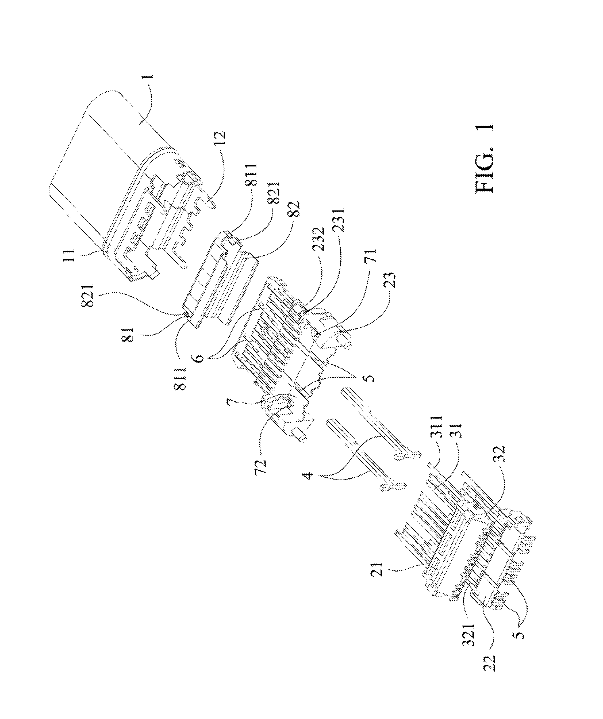
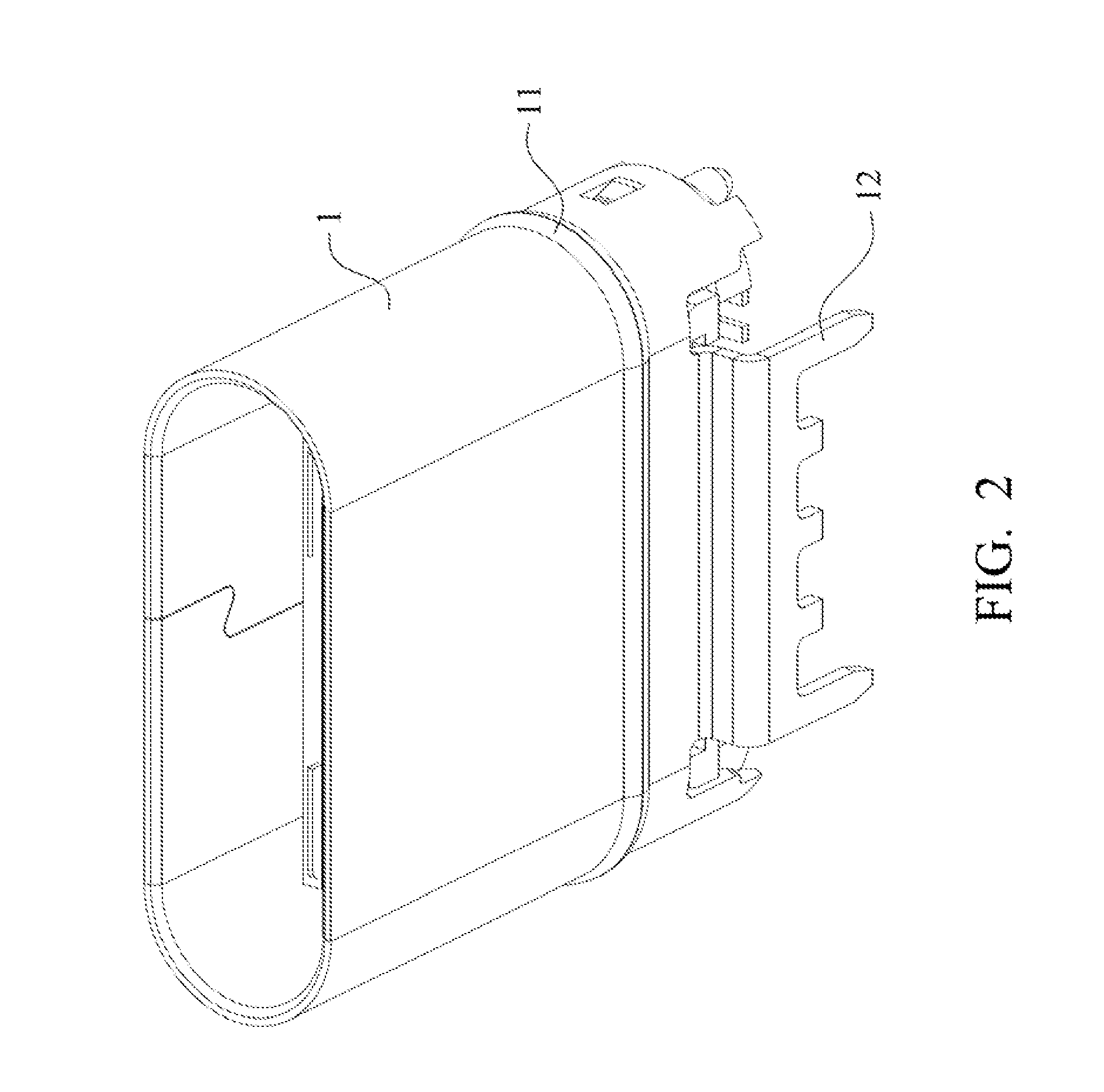
[0028]FIG. 1 to FIG. 6 disclose a first embodiment of a large current female connector for high-speed transmission. Referring to FIG. 1 to FIG. 3 first, the insulating body includes an upper insulating body 21, a middle insulating body 23, a lower insulating body 22, an upper terminal group 31 disposed on the upper insulating body 21, and a lower terminal group 32 disposed on the lower insulating body 22. The corresponding two power terminals in the upper terminal group 31 and the lower terminal group 32 are connected to form a big power terminal 4. Insulating body trenches 5 are disposed respectively on the upper insulating body 21, the middle insulating body 23, and the lower insulating body 22. When the upper terminal group 31 is disposed on the upper insulating body 21 and the lower terminal group 32 is disposed on the lower insulating body 22, the big power terminals 4 are disposed correspondingly in the insulating body trench 5 on the upper insulating body 21 and in the insula...

Example

[0033]The present invention can be implemented as a second embodiment (not shown in the figures). The second embodiment is essentially the same as the first embodiment, except that the insulating body includes an upper insulating body and a lower insulating body, in which the upper terminal group is disposed on the upper insulating body, and the lower terminal group is disposed on the lower insulating body. Insulating body trenches are disposed respectively on the upper insulating body and the lower insulating body. When the upper terminal group is disposed on the upper insulating body and the lower terminal group is disposed on the lower insulating body, the big power terminal is disposed correspondingly in the insulating body trench on the upper insulating body and in the insulating body trench on the lower insulating body. The upper insulating body and the lower insulating body are engaged with each other to form an integrated device.

[0034]To reduce the signal interference betwee...

Example

[0035]The present invention can be implemented as a third embodiment (not shown in the figures). The third embodiment is essentially the same as the first embodiment, except that the insulating body is integrally formed. The upper terminal group and the lower terminal group are disposed on the insulating body. An insulating body trench for accommodating the big power terminal is disposed on the insulating body. When the upper terminal group and the lower terminal group are disposed in the insulating body, the big power terminal is disposed correspondingly in the insulating body trench. The insulating body is then disposed into the case.

[0036]To reduce the signal interference between the terminal groups, a shielding sheet is further included. The shielding sheet is inserted in the insulating body in advance. A shielding sheet trench for accommodating the big power terminal is disposed on the shielding sheet. When the upper terminal group and the lower terminal group are disposed in t...


PUM


Abstract

Provided is a large current female connector for high-speed transmission, comprising a case, an insulating body, and an upper terminal group and a lower terminal group disposed in the insulating body. The insulating body is disposed in the case. A power terminal in the upper terminal group and a corresponding power terminal in the lower terminal group are connected to form a big power terminal. An insulating body trench for accommodating the big power terminal is disposed on the insulating body. The present invention has advantages in that the fabrication process is simple and cost effective, and a large current transport is possible.

Description

RELATED APPLICATIONS[0001]This application claims priority to Chinese Patent Application Serial Number 201420499922.7, filed on Sep. 2, 2014. The entirety of the aforementioned application is hereby incorporated by reference and made a part of this specification.BACKGROUND[0002]1. Field of Invention[0003]The present invention is related to a female connector, and more particularly, to a large current female connector for high-speed transmission.[0004]2. Description of Related Art[0005]With the popularity of the large-screen mobile terminal, the accompanying high power consumption has become an urgent issue that people have to address. To solve this problem, high-capacity batteries are developed, but the charging current for a high-capacity battery is limited by the USB connector. The dimension of a standard power terminal cannot be changed, and thus the standard power terminal can only carry limited current. The higher the electric capacity of a battery is, the longer the charging t...

Claims


Application Information

Patent Timeline
IPC IPC(8): H01R13/6585H01R13/6597H01R24/60
CPCH01R13/6585H01R2107/00H01R13/6597H01R24/60H01R13/6581
Inventor LENG, QIANGKUANG, HONG-GUANGZHENG, JIA-MAO
Owner BIZCONN INT CORP (SHEN ZHEN)
Why Eureka
Try Eureka