Solar Energy Conversion and Transmission System and Method

a transmission system and solar energy technology, applied in the direction of generators/motors, transportation and packaging, cosmonautic vehicles, etc., can solve the problems of increasing the risk of impact, increasing the cost of launching large satellites into space, and increasing the risk of orbital impa

Inactive Publication Date: 2016-03-03
WOODS JAMES JOSHUA
View PDF7 Cites 36 Cited by
  • Summary
  • Abstract
  • Description
  • Claims
  • Application Information

AI Technical Summary

Benefits of technology

[0007]In one aspect of the invention, a modular satellite for converting solar energy to microwave energy and transmitting the microwave energy to the earth to be converted into electricity is disclosed. The satellite includes solar panels configured to convert solar energy into direct current; a magnetron operatively connected to the solar panels to receive the direct current and configured to convert the direct current into microwave energy; a planar wave guide antenna operatively connected to the magnetron to receive the microwave energy and direct the microwave energy to a station on earth; and a coupling system for coupling with another satellite to form an array in response to at least one of locking, unlocking, and navigational commands. The satellite has a mass equal to or less than four kilograms, and a volume equal to or less than three liters.
[0008]In another aspect of the invention, a satellite array for converting solar energy to microwave energy and transmitting the microwave energy to the earth to be converted into electricity includes multiple satellites coupled together to form the array. Each satellite includes one or more solar panels configured to convert solar energy into direct one or more solar panels configured to convert solar energy into direct current; a magnetron operatively connected to the solar panels to receive the direct current and configured to convert the direct current into microwave energy; and one or more wave guides operatively connected to the magnetron to receive the microwave energy and direct the microwave energy to a station on earth. The satellites are all coupled such that the solar panels of each satellite face the sun, and the wave guides face the earth. The array generates and transmits to earth microwave energy with a frequency in the range of fourteen and seven tenths gigahertz to eighteen and seven tenths gigahertz.
[0009]In another aspect of the invention, a method for converting solar energy solar energy to microwave energy with an array of satellites and transmitting the microwave energy to the earth to be converted into electricity is disclosed. The array of satellites includes multiple satellites. Each satellite includes at least one solar panel, wave guide, and magnetron. Each satellite has a mass equal to or less than four kilograms. The method includes transporting each of the satellites in the array to a space station with a cargo load for the space station, and launching each of the satellites into a geo-stationary low earth orbit between fifty-two degree latitude north and fifty-two degree latitude south from the space station. The method also includes coupling all the satellites together in an array wherein the solar panels of each satellite face the sun, and the wave guides face the earth; and converting solar energy into direct current with the solar panel of at least one satellite. The method also includes converting the direct current into microwave energy with the magnetron of at least one satellite, the microwave energy having a frequency in the range of fourteen and seven tenths gigahertz and eighteen to seven tenths gigahertz; transmitting the microwave energy to a station on earth with the wave guide of at least one satellite; and converting the microwave energy into one of alternating current or direct current to power a consumer load on earth.

Problems solved by technology

Numerous obstacles have existed to making a solar satellite farm a reality.
Launching large satellites into space is expensive.
But, unlike a low earth orbit nearer the equator, these orbits may be more prone to impacts from solar storm activity.
Many devices, including communication devices, operate in this range of frequencies and it may be difficult to get administrative approval to use them.

Method used


Image

  • Solar Energy Conversion and Transmission System and Method
  • Solar Energy Conversion and Transmission System and Method
  • Solar Energy Conversion and Transmission System and Method

Examples


Embodiment Construction

[0049]The following detailed description is of the best currently contemplated modes of carrying out the invention. The description is not to be taken in a limiting sense, but is made merely for the purpose of illustrating the general principles of the invention, since the scope of the invention is best defined by the appended claims.

[0050]Various inventive features are described below that can each be used independently of one another or in combination with other features. However, any single inventive feature may not address any of the problems discussed above, or may only address one of the problems discussed above. Further, one or more of the problems discussed above may not be fully addressed by any of the features described below.

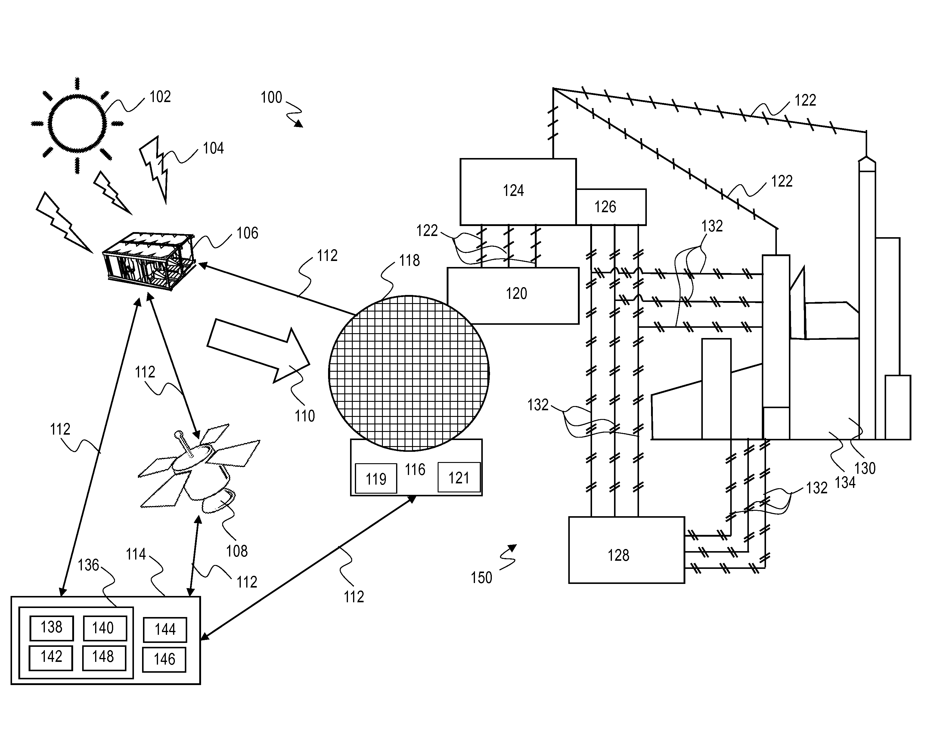
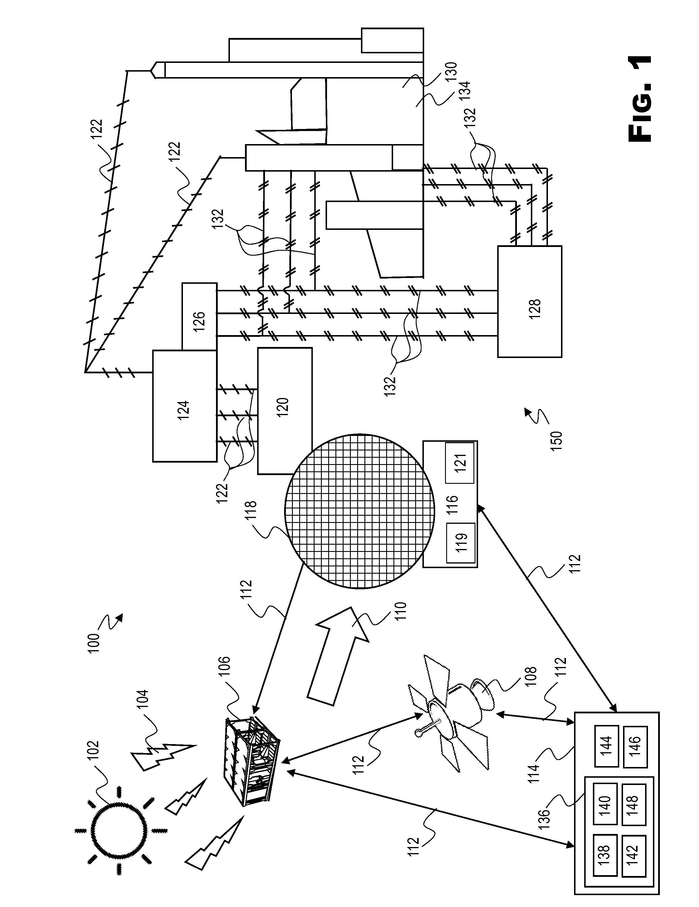
[0051]Satellites for use in space solar energy farms to convert and transmit energy to earth for use in powering loads on earth, may need to have adequate surface area on solar panels to convert and transmit enough energy to make building receiver sta...


PUM


Abstract

A modular satellite for converting solar energy to microwave energy and transmitting the microwave energy to the earth to be converted into electricity includes solar panels configured to convert solar energy into direct current; a magnetron operatively connected to the solar panels to receive the direct current and configured to convert the direct current into microwave energy; a planar wave guide antenna operatively connected to the magnetron to receive the microwave energy and direct the microwave energy to a station on earth; and a coupling system for coupling with another satellite to form an array in response to at least one of locking, unlocking, and navigational commands. The satellite has a mass equal to or less than four kilograms, and a volume equal to or less than three liters.

Description

PRIORITY[0001]This application claims priority to and incorporates by reference in its' entirety, U.S. Provisional Patent Application No. 62 / 044,360, entitled “Solar Energy Conversion and Transmission System and Method”, and filed Sep. 1, 2014.TECHNICAL FIELD[0002]The present invention generally relates to systems and methods to for converting solar power to microwave electric energy, transmitting the microwaves to earth, and converting the microwaves to usable electric energy. More particularly the present invention relates to converting solar energy to microwave energy with modular satellites.BACKGROUND[0003]In the past two decades there have been numerous proposals to deploy solar satellite farms to convert solar energy from the sun into usable electrical energy on earth. Numerous obstacles have existed to making a solar satellite farm a reality. For a conversion station on earth to be commercially viable, solar panels on the satellites must have a large enough surface area to co...

Claims


Application Information

Patent Timeline
Patent Type & Authority Applications(United States)
IPC IPC(8): B64G1/00B64G1/44
CPCH02J17/00B64G1/007B64G1/443B64G1/002B64G1/1085B64G1/242B64G1/283B64G1/36B64G1/361B64G1/363B64G1/365B64G1/366B64G1/428B64G1/44B64G1/64B64G1/66H02J50/23H02J50/27H02J50/40B64G1/223B64G1/369B64G1/2427H02J50/30
Inventor WOODS, JAMES, JOSHUA
Owner WOODS JAMES JOSHUA
Why Eureka
Try Eureka