Stop control device of vehicle

a technology of stop control device and vehicle, which is applied in the direction of steering initiation, vessel construction, instruments, etc., can solve the problems of unintended backward movement or the like of the vehicle, the difficulty of pinwheel driving operation, and the lateral movemen

Inactive Publication Date: 2016-03-10
NTN CORP
View PDF4 Cites 8 Cited by
  • Summary
  • Abstract
  • Description
  • Claims
  • Application Information

AI Technical Summary

Benefits of technology

[0008]An object of the present invention is to provide a vehicle stop control device configured to prevent, when a traveling mode is switched, unintended movement of a vehicle in which all wheels are capable of being independently turned, and which can travel in a non-normal mode.
[0018]In this configuration, the mode is switched among the lateral movement mode, the pinwheeling mode, the normal traveling mode, and the parking mode by the traveling mode switching section 41. For example, after the vehicle has reached a destination in the normal traveling mode, a driver operates the traveling mode switching section 41, whereby the mode can be switched to the lateral movement mode or the pinwheeling mode. Thus, garaging, movement to a parking space, direction change in a narrow space or the like can be performed easily. Therefore, with the operation of the traveling mode switching section 41, the traveling mode can be switched. When the mode is switched by the traveling mode switching section 41, the turning timing shift part 32c shifts the timing for turning at least one of all the wheels 1, 2 relative to the timing for turning the other wheels. At the time of mode switching, a plurality of wheels 1, 2 to be turned are not simultaneously turned, but the timing for turning at least one of the plurality of wheels 1, 2 is shifted, whereby a frictional force constantly acts between a road surface and any of the wheels 1, 2 at the time of mode switching. Thus, unintended movement of the vehicle due to disturbance such as an inclination can be prevented. Therefore, unintended movement of the vehicle at the time of switching the traveling mode can be prevented.
[0019]The turning timing shift part 32c may shift timing for turning front wheels 1 relative to timing for turning rear wheels 2. For example, when the mode is switched from the lateral movement mode to the parking mode, the turning timing shift part 32c causes the turning devices 4 to perform turning so as to delay the timing for turning the left and right front wheels 1, 1 relative to the timing for turning the left and right rear wheels 2, 2. Thus, at the time of mode switching, the turning timing is shifted such that the front and rear wheels 1, 2 do not become parallel to each other simultaneously, whereby unintended movement of the vehicle on a slope or the like can be prevented.
[0020]The turning timing shift part 32c may shift timing for turning front and rear right wheels 1, 2 relative to timing for turning front and rear left wheels 1, 2. For example, when the mode is switched from the lateral movement mode to the parking mode, the turning timing shift part 32c causes the turning devices 4 to perform turning so as to delay the timing for turning the front and rear right wheels 1, 2 relative to the timing for turning the front and rear left wheels 1, 2. Thus, unintended movement of the vehicle on a slope or the like can be prevented. The turning timing shift part 32c may shift the timing for turning all the wheels 1, 2.
[0021]A stopped-state turning control part 32b may be provided which is configured to cause the turning devices 4 to turn one or more of the wheels 1, 2 toward a toe-in or toe-out side by an amount greater than a defined turning amount command value, to perform hill hold of the vehicle, after mode switching by the traveling mode switching section 41. On a slope or the like, unintended movement of the vehicle may occur even after the mode has been switched. With this configuration, after the mode switching, the stopped-state turning control part 32b causes the respective turning devices 4 corresponding to one or more wheels 1, 2 to turn the one or more wheels 1, 2 toward a toe-in or toe-out side by an amount greater than a defined turning amount command value. A frictional force between a road surface and the turned wheels can prevent unintended movement of the vehicle.

Problems solved by technology

[Patent Document 1] JP Patent No. 4541201 In the car that can travel in the non-normal mode, it is difficult to perform driving operation for the pinwheeling, the lateral movement, or the like, by operating a steering wheel and an accelerator pedal.
Further, it is sometimes difficult to perform appropriate driving operation according to the situation, by automatic driving operation by means of dedicated buttons operation.
Therefore, when a vehicle performs switching of the mode on a slope or the like, unintended backward movement or the like of the vehicle may occur due to the inclination of a slope.

Method used


Image

  • Stop control device of vehicle
  • Stop control device of vehicle
  • Stop control device of vehicle

Examples


Embodiment Construction

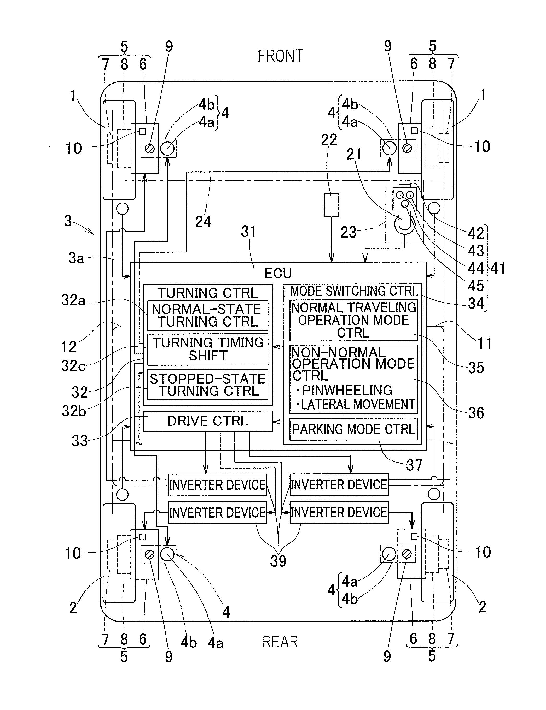
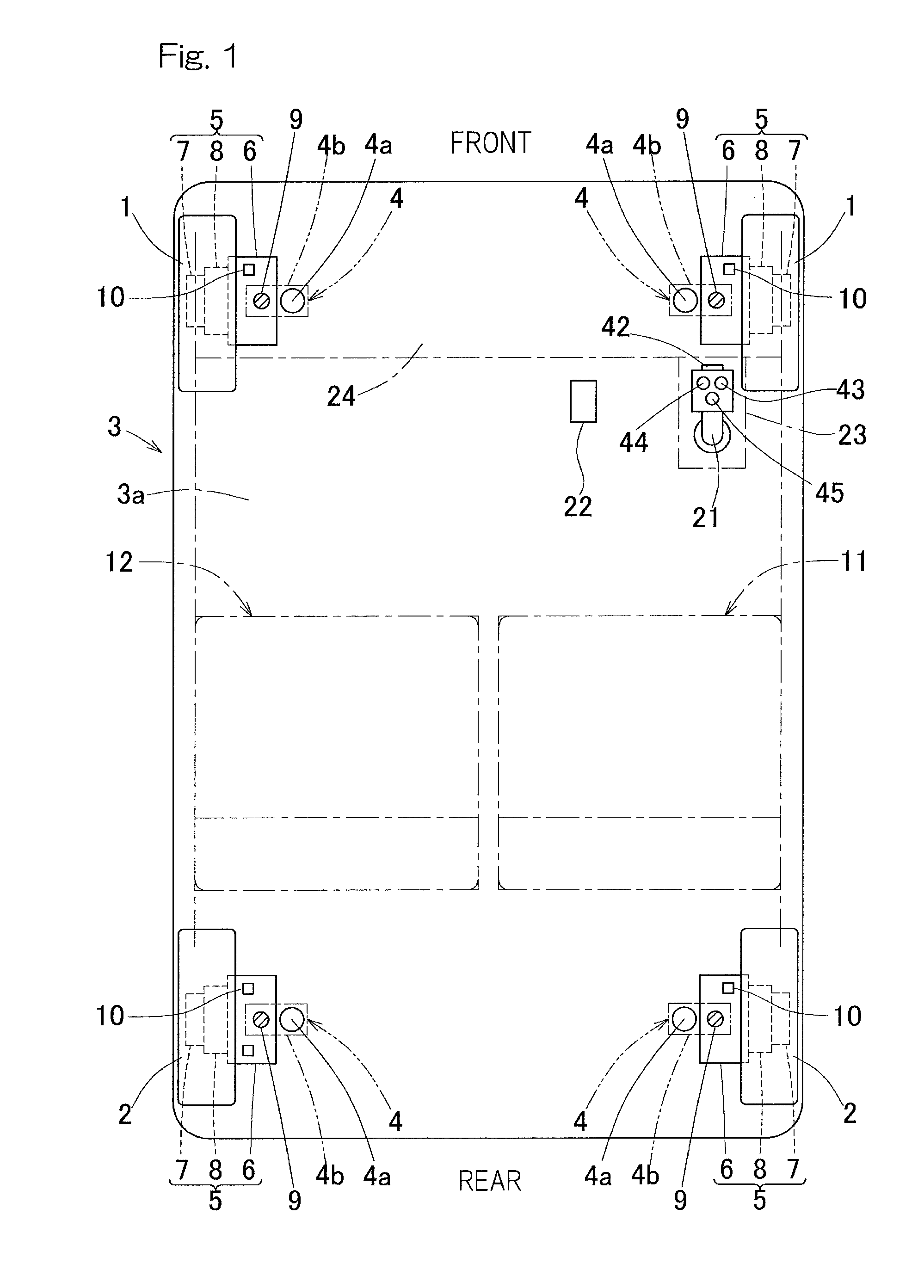
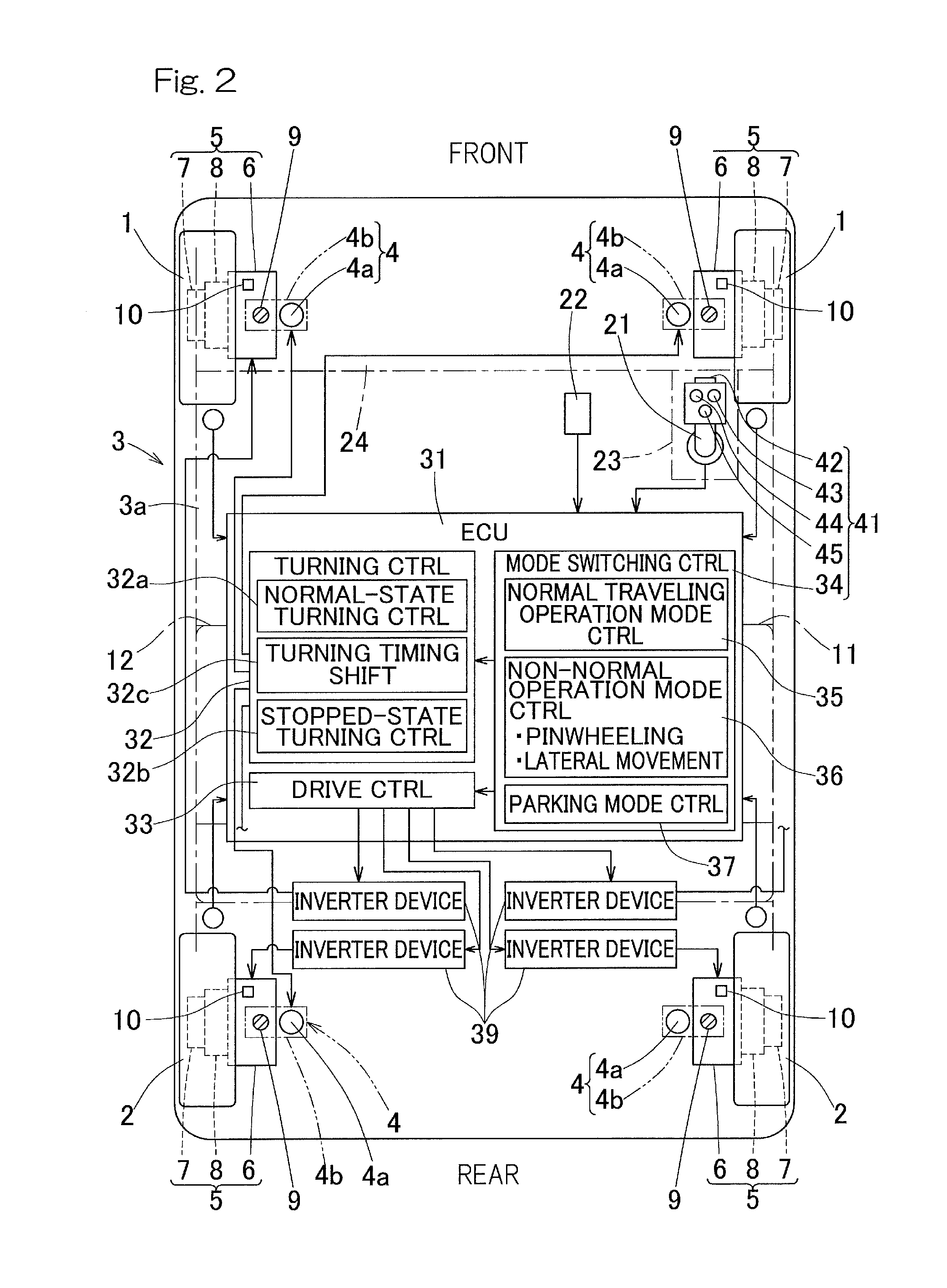
[0036]A first embodiment of the present invention will be described with reference to FIG. 1 to FIG. 6. A vehicle according to the present embodiment is an electric car which has two left and right wheels 1, 1 serving as front wheels and two left and right wheels 2, 2 serving as rear wheels. All the wheels 1, 2 each include a turning device 4 which allows independent turning of its corresponding wheel. In an illustrated example, the wheels 1, 2 are all driven wheels that are each independently driven to travel by a traveling drive mechanism 5 that includes a drive source 6.

[0037]In this example, the traveling drive mechanism 5 is an in-wheel motor drive device including a wheel bearing 7 supporting the corresponding wheel 1, 2, a motor 6 serving as a drive source, and a speed reducer or reduction gear 8 for reducing the speed of the rotation outputted from the motor 6 and for transmitting the rotation to a rotational bearing ring (not shown) of the wheel bearing 7. The traveling dri...


PUM


Abstract

A vehicle stop control device is provided which prevents, when a traveling mode is switched, unintended movement of a vehicle in which all wheels are capable of being independently turned, and which can travel in a non-normal mode. Provided is: traveling mode switching section which can switch among a lateral movement mode, a pinwheeling mode, a normal traveling mode, and a parking mode, as a control mode for selecting operation combined by turning devices and traveling drive mechanisms; and turning timing shift part configured to shift the timing for turning at least one of all the wheels relative to the timing for turning the other ones of the wheels at the time of mode switching by the traveling mode switching section.

Description

CROSS REFERENCE TO THE RELATED APPLICATION[0001]This application is a continuation application, under 35 U.S.C. §111(a), of international application No. PCT / JP2014 / 063552, filed May 22, 2014, which is based on and claims Convention priority to Japanese patent application No. 2013-114949, filed May 31, 2013, the entire disclosure of which is herein incorporated by reference as a part of this application.BACKGROUND OF THE INVENTION[0002]1. Field of the Invention[0003]The present invention relates to a vehicle stop control device configured to prevent unintended backward movement or the like of a vehicle in which all wheels are capable of being independently turned and driven wheels are capable of being independently driven to travel.[0004]2. Description of Related Art[0005]Electric cars or the like in which all wheels are capable of being independently turned and driven wheels are capable of being independently driven to travel, have been suggested. Such cars can move in a special mo...

Claims


Application Information

Patent Timeline
Patent Type & Authority Applications(United States)
IPC IPC(8): B62D7/15B60L15/20B62D15/02B62D17/00
CPCB62D7/1509B60L15/2036B62D17/00B62D15/027B60L15/025B60L2220/44B60L2240/423B60L2250/24B60L2250/26B60L2260/28B60L50/51Y02T10/64Y02T10/70Y02T10/72
Inventor MATSUOKA, DAISUKE
Owner NTN CORP
Why Eureka
Try Eureka