Vehicle body manufacturing apparatus

a manufacturing apparatus and vehicle body technology, applied in the direction of manufacturing tools, drawing boards, printing, etc., can solve the problems of interfering with the movement of welding, and achieve the effect of accurate positioning of the work of the vehicle body

Active Publication Date: 2016-03-10
SUBARU CORP
View PDF4 Cites 20 Cited by
  • Summary
  • Abstract
  • Description
  • Claims
  • Application Information

AI Technical Summary

Benefits of technology

[0008]The present invention has been made in view of the above-described situation and aims to provide a vehicle body manufacturing

Problems solved by technology

Therefore, when pre-assembly welding is performed, various mechanical units for supporting the clamp jigs are disp

Method used


Image

  • Vehicle body manufacturing apparatus
  • Vehicle body manufacturing apparatus
  • Vehicle body manufacturing apparatus

Examples


Embodiment Construction

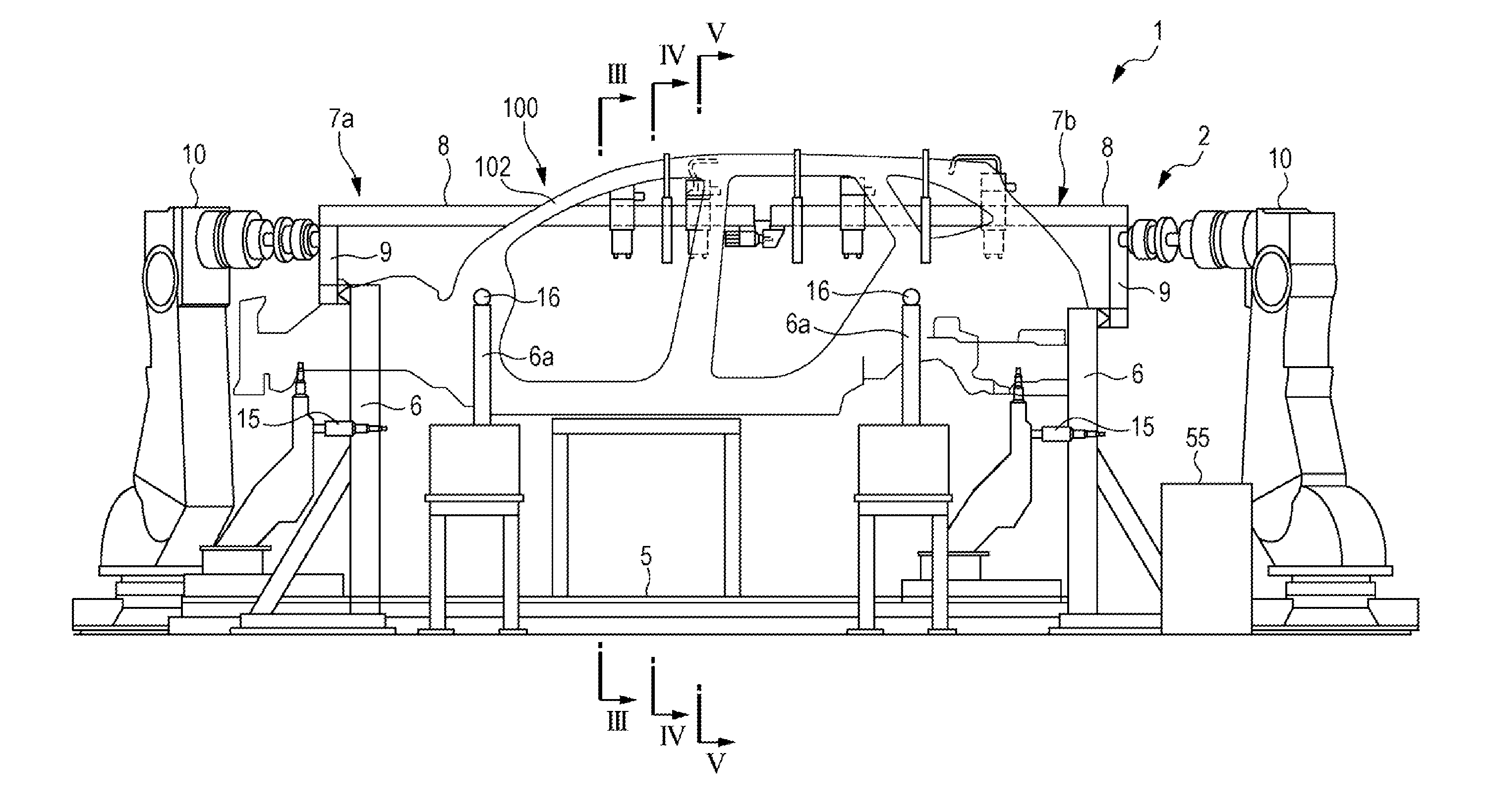
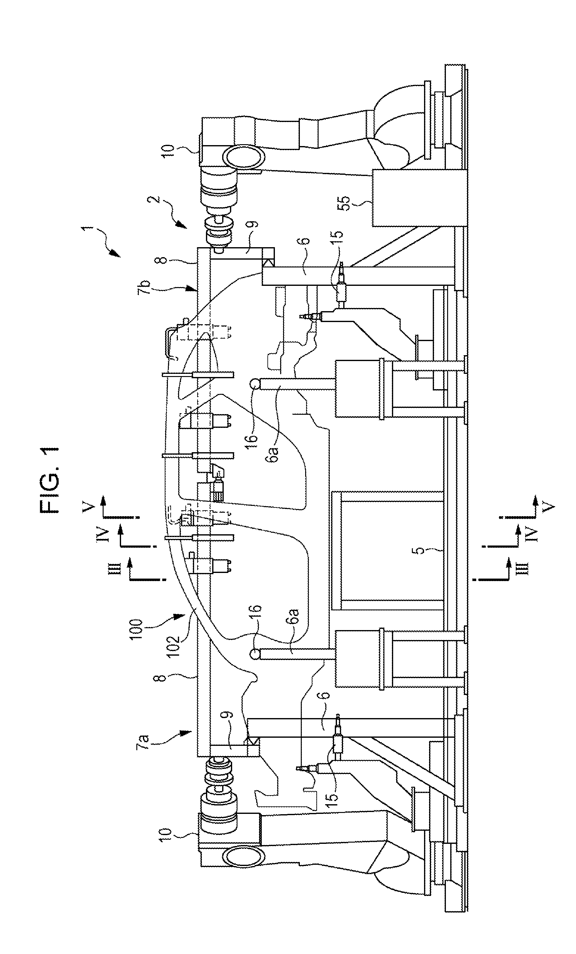
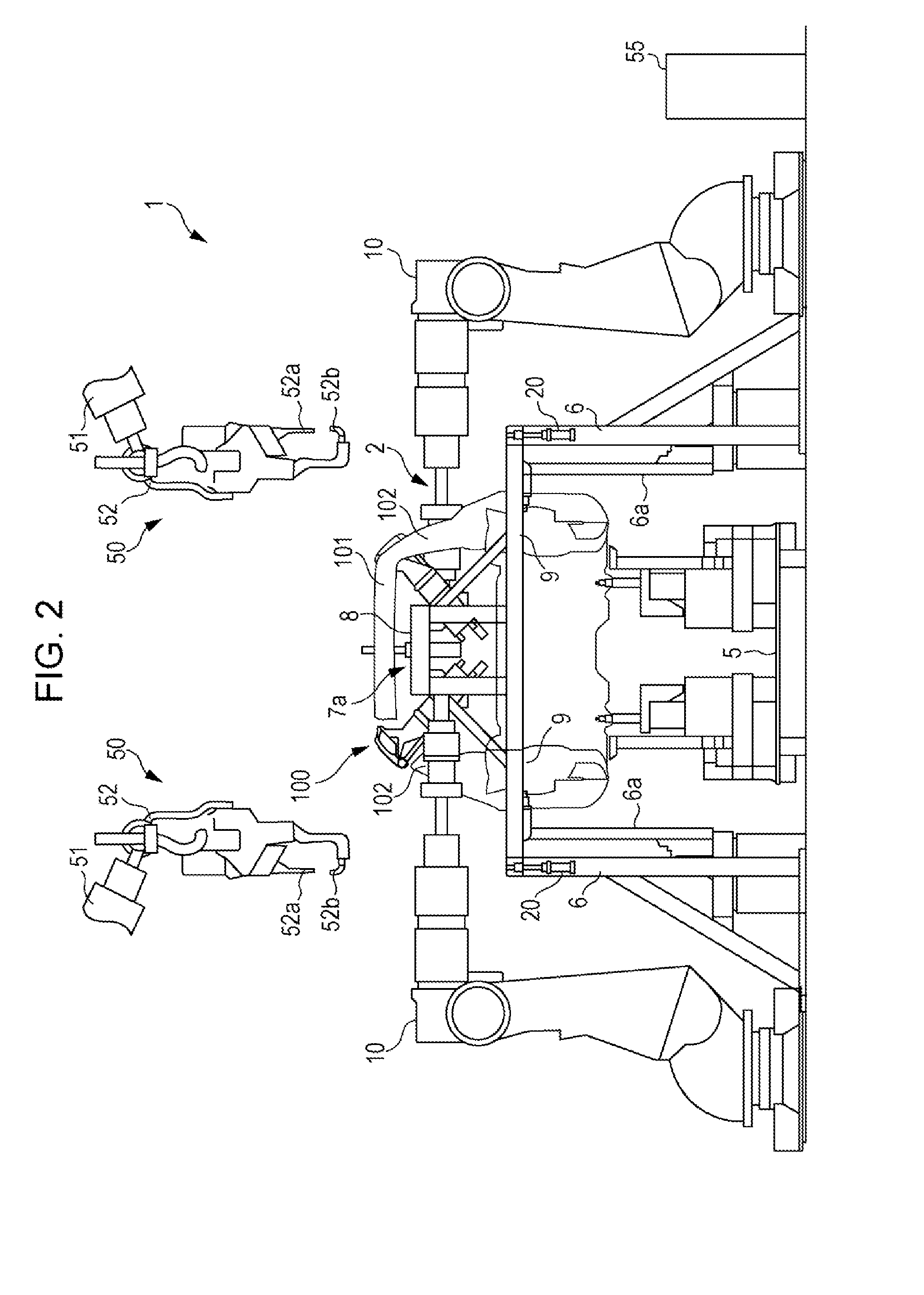
[0020]Hereinafter, an implementation of the present invention will be described with reference to the drawings. The drawings are related to the implementation of the present invention. FIG. 1 is a side view illustrating the schematic configuration of a vehicle body manufacturing apparatus; FIG. 2 is a front view illustrating the schematic configuration of the vehicle body manufacturing apparatus; FIG. 3 is a view as seen in the direction of arrows III-III of FIG. 1; FIG. 4 is a view as seen in the direction of arrows IV-IV of FIG. 1; FIG. 5 is a view as seen in the direction of arrows V-V of FIG. 1; FIG. 6 is a side view illustrating a connection member; FIG. 7 is a side view illustrating an upper clamp jig; FIG. 8 is a front view illustrating the locking mechanism between a side jig frame and an upper jig frame; and FIGS. 9 and 10 are a flow chart illustrating pre-assembly welding process for structures including side structures.

[0021]A vehicle body manufacturing apparatus 1 illust...


PUM


Abstract

A vehicle body manufacturing apparatus includes: side jig frames disposed respectively on the right and left sides of a vehicle body; an upper jig frame installed between the side jig frames, the upper jig frames including a pair of front and rear frame members insertable into the inside of the vehicle body through front and rear openings of the vehicle body, respectively; a connection mechanism that removably connects insertion ends of the pair of frame members; and a clamping mechanism that is held on the upper jig frame and that positions the vehicle body.

Description

CROSS-REFERENCE TO RELATED APPLICATIONS[0001]The present application claims priority from Japanese Patent Application No. 2014-180550 filed on Sep. 4, 2014, the entire contents of which are hereby incorporated by reference.BACKGROUND[0002]1. Technical Field[0003]The present invention relates to vehicle body manufacturing apparatuses that weld one work of a temporarily fixed vehicle body to another work to pre-assemble the vehicle body.[0004]2. Related Art[0005]There have been proposed and put into practical use various techniques for assembling a vehicle body by spot welding multiple works included in the vehicle body with the works positioned.[0006]As a vehicle body manufacturing apparatus of this type, for instance, Japanese Published Examined Patent Application Publication (JP-B) No. 6-59851 discloses a technique that uses a vehicle body manufacturing apparatus to assemble multiple types of vehicle body having shapes at clamp positions of the vehicle body in common between vehicl...

Claims


Application Information

Patent Timeline
IPC IPC(8): B62D65/02
CPCB62D65/026B25B11/02
Inventor SAKAMOTO, NOBORU
Owner SUBARU CORP
Why Eureka
Try Eureka