Pile hammer

Inactive Publication Date: 2016-03-10
DELMAG
View PDF10 Cites 0 Cited by
  • Summary
  • Abstract
  • Description
  • Claims
  • Application Information

AI Technical Summary

Benefits of technology

[0016]In a further embodiment of the invention, the buffer part is configured to be elastic, at least in certain regions, and/or elastically mounted on the carriage. In this way, a gentle impact of the buffer body against the stop is brought about when the at least one cable is tensed.
[0017]In a further embodiment of the invention, the cable that runs around the guide anchor is connected with a traverse at its two ends, which traverse has an accommodation for a crane cable. In this way, optimal single-cable handling by way of the crane cable of a crane is made possible. Preferably, the accommodation is formed by a shackle for accommodating a crane hook.
[0018]In a further embodiment of the invention, the stop that projects outward has a contact piece t

Problems solved by technology

It is a disadvantage of the previously known pile hammer that when the pile hammer is set up from a horizontal position by way of the crane cable, it can occur that the outer holding cables come to lie around the guide rails of the disengagement apparatus, which rails can be damaged when these cables are pulled.
Furthermore, it can occur that in the case of disadvantageous positioning of the cables, the main weight of the pile hammer lies on the center cable connected with the disengagement apparatus, thereby resul

Method used


Image

  • Pile hammer
  • Pile hammer
  • Pile hammer

Examples


Example

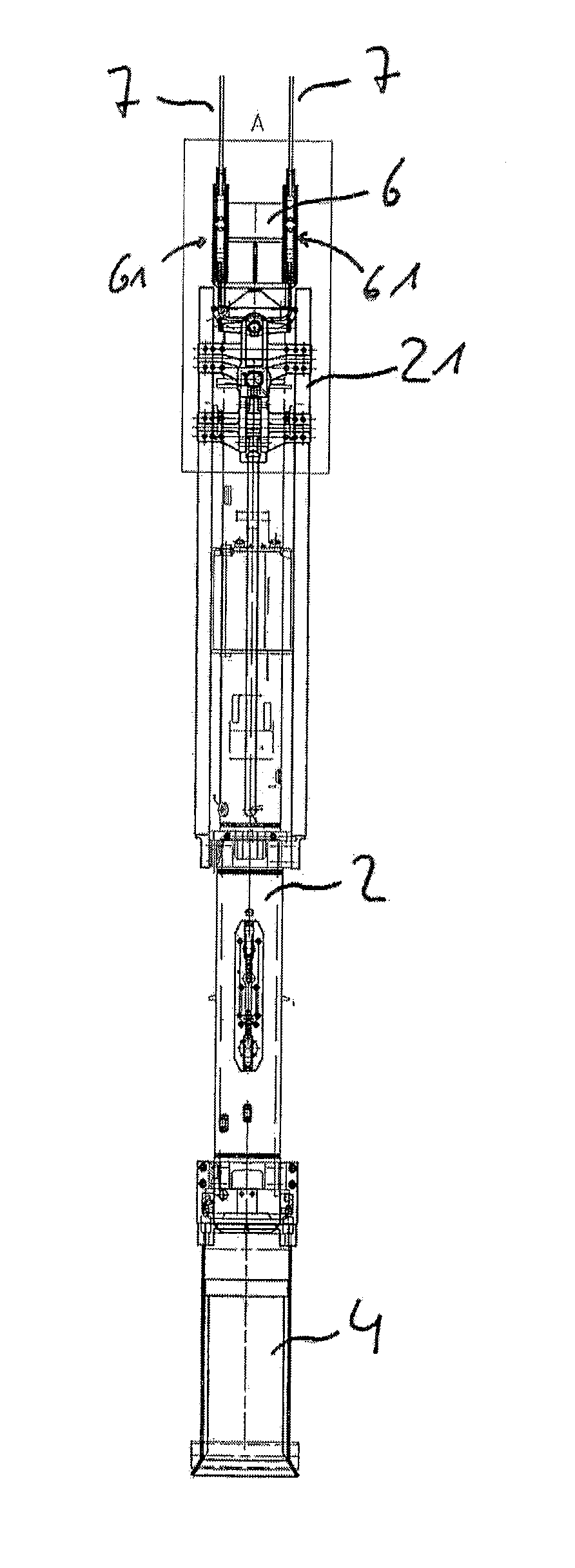
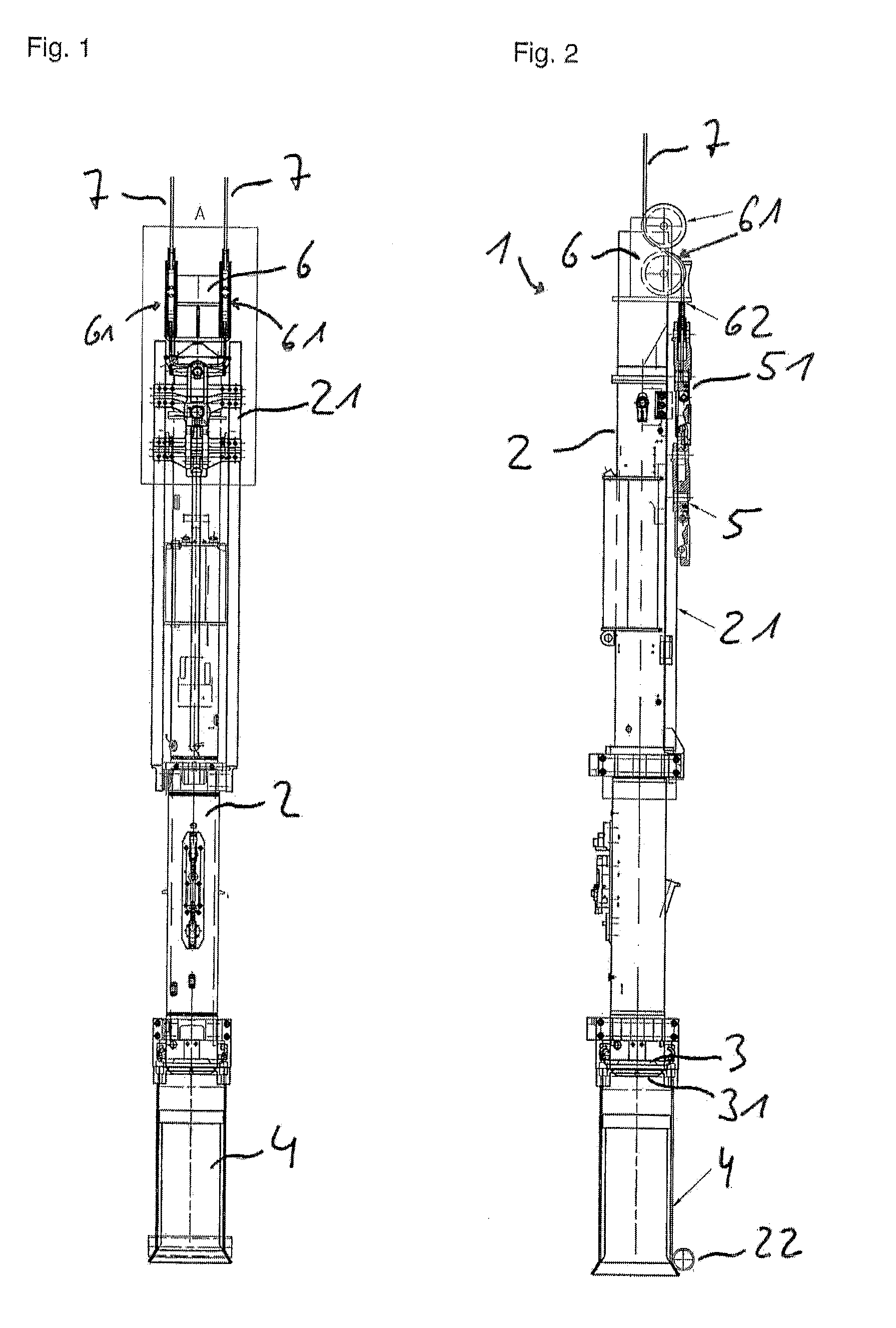
[0027]Referring now in detail to the drawings, the pile hammer shown in FIGS. 1 and 2 selected as an exemplary, embodiment is configured as a diesel hammer 1. The diesel hammer 1 has a cylinder 2 that is open on both sides, and regularly can have a length of 3 to 8 meters and a diameter of 0.2 to 1.5 meters. A piston—not shown—is displaceably disposed in the cylinder. A striker 3 coaxial to the piston engages into the open lower end of the cylinder 2, in displaceable manner. A striker plate 31 is formed onto the striker 3; its lower delimitation surface, directed outward, interacts with the upper end of a concrete pillar to be pile-driven during operation. In the exemplary embodiment, a pile ram chisel 4 for accommodating material to be pile-driven is disposed below the striker plate 31.

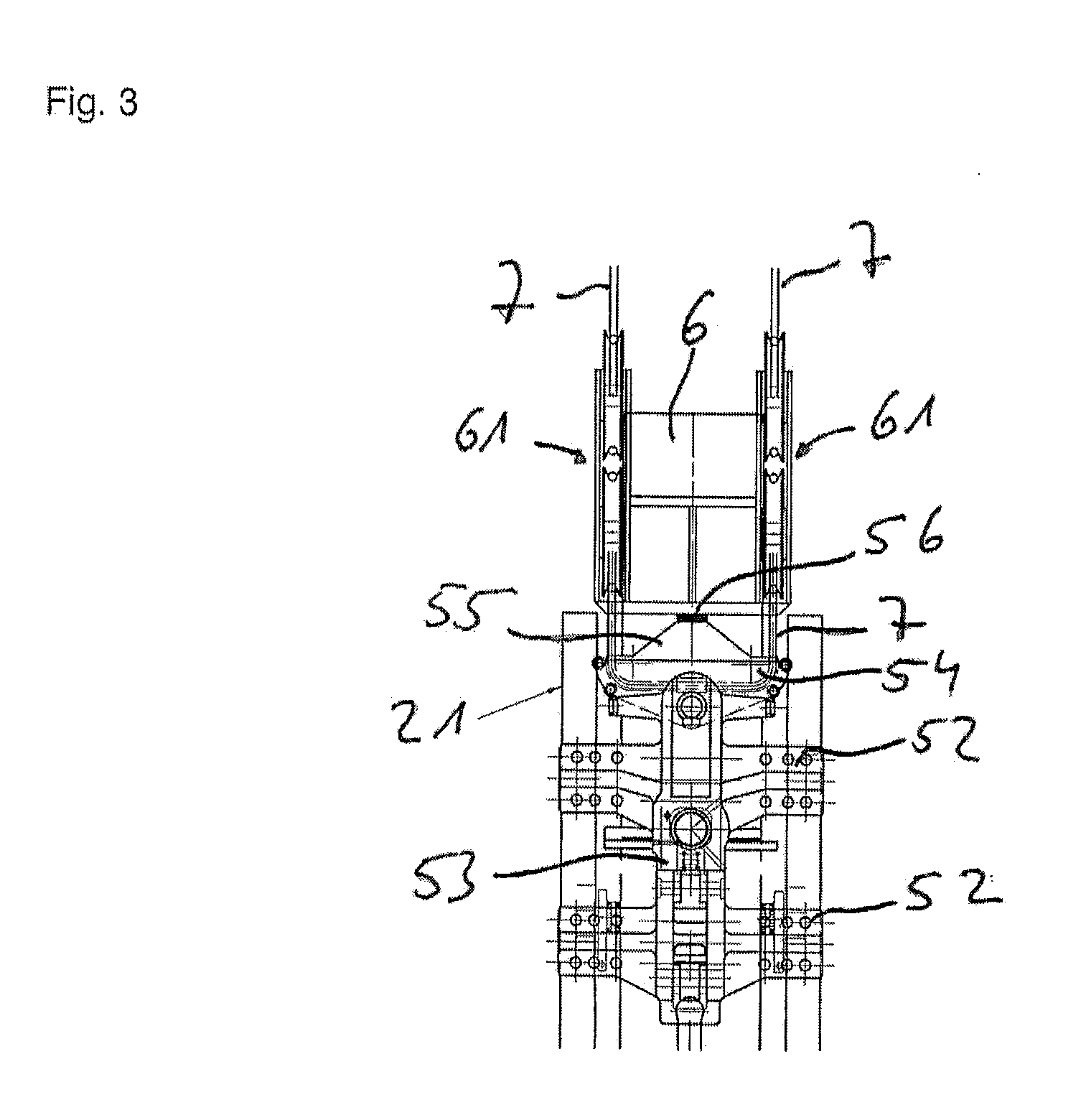
[0028]Two guide spars 21 are attached on the outside of the cylinder, parallel to one another, on which the carriage 51 of a disengagement apparatus 5 is guided so as to be displaceable.

[0029]The car...


PUM


Abstract

A pile hammer includes a cylinder, a piston displaceably guided in the cylinder, a striker displaceably guided in the cylinder and disposed underneath the piston in the operating position of the pile hammer, a combustion chamber delimited axially by a face surface of the striker that lies in the interior of the cylinder and by a face surface of the piston, as well as a disengagement apparatus by way of which the piston can be moved in the cylinder, into an upper position, wherein the disengagement apparatus includes a carriage, which is connected with at least one cable, by way of which the carriage is guided to be displaceable on the outside, along the cylinder, wherein a stop that projects outward is disposed on the cylinder and a buffer part is disposed on the carriage, with which part the carriage lies against the stop in an upper end position.

Description

CROSS REFERENCE TO RELATED APPLICATIONS[0001]Applicant claims priority under 35 U.S.C. §119 of European Application No. 14184318.5 filed Sep. 10, 2014, the disclosure of which is incorporated by reference.BACKGROUND OF THE INVENTION[0002]1. Field of the Invention[0003]The invention relates to a pile hammer comprising a cylinder, a piston displaceably guided in the cylinder, a striker displaceably guided in the cylinder, which striker is disposed below the piston in the operating position of the pile hammer, a combustion chamber that is delimited axially by a face surface of the striker that lies in the interior of the cylinder and a face surface of the piston, as well as a disengagement apparatus by way of which the piston can be moved in the cylinder, into an upper position.[0004]2. Description of the Related Art[0005]Such pile hammers, such as diesel hammers, which are also called diesel pile drivers, are particularly used in foundation work in the construction industry. The pile ...

Claims


Application Information

Patent Timeline
IPC IPC(8): E02D7/12
CPCE02D7/125
Inventor HEICHEL, MATTHIASHEINZ, NIKODEMUS
Owner DELMAG
Why Eureka
Try Eureka