Supercharge Your Innovation With Domain-Expert AI Agents!

Fluid leakage counteraction instrument upon damage of fluid conveying pipe

a technology of fluid conveying pipe and counteraction instrument, which is applied in the direction of branching pipes, mechanical equipment, pipe elements, etc., can solve the problems of affecting the maintenance operation, affecting the maintenance effect, so as to achieve convenient maintenance operation and very economical

Inactive Publication Date: 2016-03-10
CHOI SANG HWAN
View PDF8 Cites 5 Cited by
  • Summary
  • Abstract
  • Description
  • Claims
  • Application Information

AI Technical Summary

Benefits of technology

The present invention is a fluid leakage counteraction instrument for repairing damaged fluid conveying pipes. It is designed to quickly recover the damaged part of the pipe and prevent fluid leakage. The instrument consists of a recovery tubular body with a pad for attachment to the damaged part of the pipe and a valve for controlling fluid leakage. The instrument also includes a fixing means to secure the pad to the pipe. This means may include a fixture and a clamp to press the pad against the pipe. A discharge tubular body can be inserted into the pipe through the damaged part to discharge the fluid under pressure difference. The instrument also includes a curved pad with an adhesion means to closely attach it to the pipe, a pad fixing magnet for easy installation, and a packing member for watertight seal. Overall, the instrument helps to quickly and effectively repair damaged fluid conveying pipes.

Problems solved by technology

These conveying pipes are one of the very important facilities and usually take charge of normal convey of fluid, however, in some cases, the conveying pipes are damaged due to excessive load, aging or external factor so that the fluid is leaked.
If the conveying pipes are damaged and the fluid is leaked as such, the operator closes the valve right away and replaces with new pipes or repairs by using joint coupling, however, there is a problem in that these operations are annoying and take a lot of times.

Method used


Image

  • Fluid leakage counteraction instrument upon damage of fluid conveying pipe
  • Fluid leakage counteraction instrument upon damage of fluid conveying pipe
  • Fluid leakage counteraction instrument upon damage of fluid conveying pipe

Examples


Embodiment Construction

[0026]Hereinafter, a preferred embodiment of the present invention will be described in more detail with reference to the accompanying drawings.

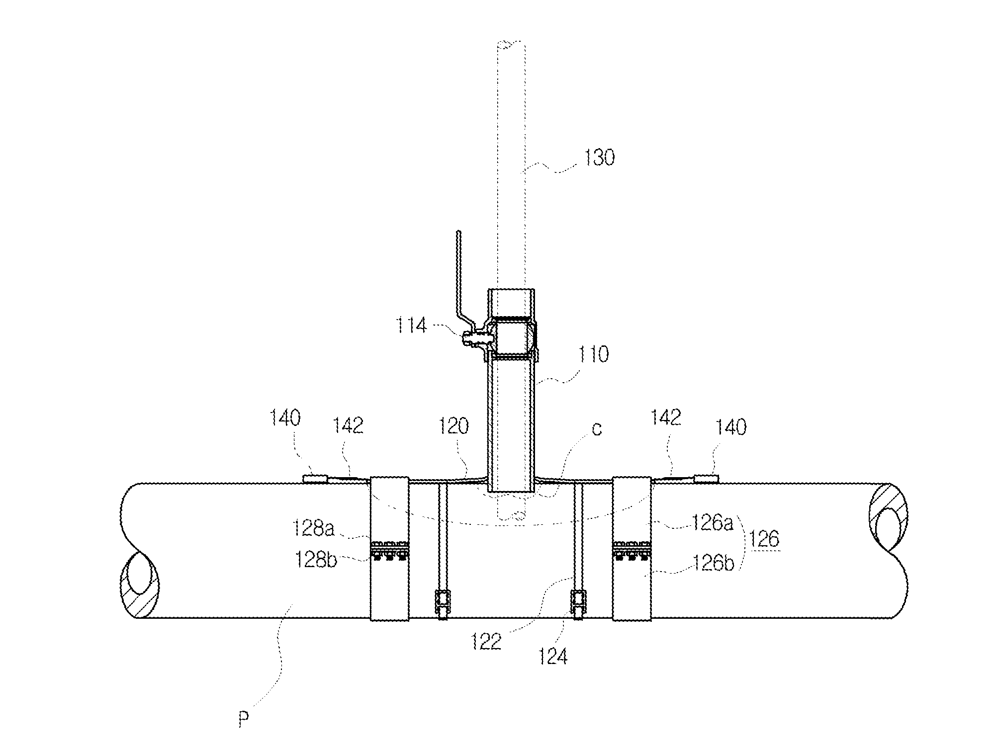
[0027]As shown in the drawings, a fluid leakage counteraction instrument upon damage of fluid conveying pipe according to the present invention is installed to rapidly recover the damaged part in case where the conveying pipe which conveys the fluid such as the liquid and the gas is damaged.

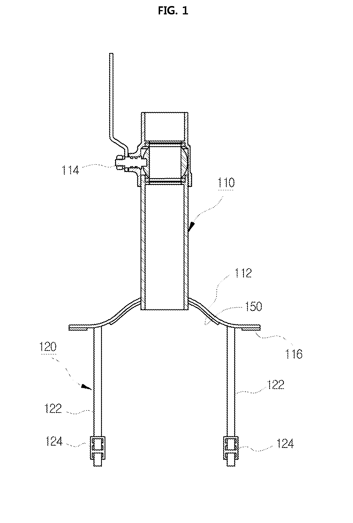
[0028]This fluid leakage counteraction instrument upon damage of fluid conveying pipe according to the present invention is provided with a recovery tubular body 110. The recovery tubular body 110 is installed with a pad 112 at its one end in such a way that the pad 112 can be closely attached to the damaged part of the conveying pipe P, and the recovery tubular body 110 is installed with a valve 114 at its other end.

[0029]Here, the pad 112 can be composed by a material such as the metal material or the rubber material, and in a case where the pad 112 is ...


PUM

PropertyMeasurementUnit
Pressureaaaaaaaaaa
Circumferenceaaaaaaaaaa

Abstract

The object of the present invention is to provide a fluid leakage counteraction instrument upon damage of fluid conveying pipe which can rapidly recover the damaged part in case where the conveying pipe is damaged so that the fluid is leaked.The present invention is a fluid leakage counteraction instrument upon damage of fluid conveying pipe which is installed as to rapidly recover the damaged part of the conveying pipe which conveys the fluid, the instrument comprising: a recovery tubular body, at one end of which is installed a pad which can be closely attached to the damaged part of the conveying pipe, and at the other end of which is installed a valve; and a fixing means which can closely fix the pad installed at the recovery tubular body to the damaged part of the conveying pipe.

Description

TECHNICAL FIELD[0001]The present invention relates to a fluid leakage counteraction instrument upon damage of fluid conveying pipe, and more particularly, it relates to a fluid leakage counteraction instrument upon damage of fluid conveying pipe which can rapidly recover the damaged part in case where the conveying pipe which conveys the fluid such as the liquid and the gas is damaged and the fluid is leaking.BACKGROUND OF THE INVENTION[0002]In general, it is well known that conveying pipes are installed like a spider's web in various industrial facilities or general buildings.[0003]These conveying pipes are one of the very important facilities and usually take charge of normal convey of fluid, however, in some cases, the conveying pipes are damaged due to excessive load, aging or external factor so that the fluid is leaked.[0004]If the conveying pipes are damaged and the fluid is leaked as such, the operator closes the valve right away and replaces with new pipes or repairs by usin...

Claims


Application Information

Patent Timeline
IPC IPC(8): F16L55/18F16L41/04F16L55/168
CPCF16L55/18F16L41/04F16L55/1683F16L41/12F16L41/06F16L55/172F16L55/168F16L47/30
Inventor CHOI, SANG, HWAN
Owner CHOI SANG HWAN
Features
  • R&D
  • Intellectual Property
  • Life Sciences
  • Materials
  • Tech Scout
  • Unparalleled Data Quality
  • Higher Quality Content
  • 60% Fewer Hallucinations
Learn More