Wide scan steerable antenna

a steerable antenna and wide-scan technology, applied in the direction of antennas, electric devices, etc., can solve the problems of increasing the complexity of the drive electronics system, requiring larger rotary actuators with more complex drive electronics, and increasing the cost of drive electronics, so as to avoid the need for high-speed actuation, improve the reliability of the antenna system, and optimize the antenna geometry

Active Publication Date: 2016-03-10
MACDONALD DETTWILER & ASSOC CORP
View PDF14 Cites 11 Cited by
  • Summary
  • Abstract
  • Description
  • Claims
  • Application Information

AI Technical Summary

Benefits of technology

[0007]An advantage of the present invention is that the architecture is capable of steering the beam nearly over a full hemisphere (2π steradians).
[0008]Another advantage of the present invention is that, depending on the configuration, there are no singularities or key-holes within the coverage area, therefore avoiding the need for high speed actuation of the rotary actuators and the associated complexity and cost.
[0009]A further advantage of the present invention is that the antenna architecture eliminates the need for an RF signal rotary mechanism such as RF rotary joint or flexible waveguide or flexible RF cable, slip ring or the like, therefore improvi...

Problems solved by technology

Some solutions have been developed to eliminate rotary joints in wide angle steerable antennas but they are affected by the presence of a singularity which affects the ability to track a target when the beam becomes substantially ali...

Method used


Image

  • Wide scan steerable antenna
  • Wide scan steerable antenna
  • Wide scan steerable antenna

Examples


Embodiment Construction

[0045]With reference to the annexed drawings the preferred embodiment of the present invention will be herein described for indicative purpose and by no means as of limitation.

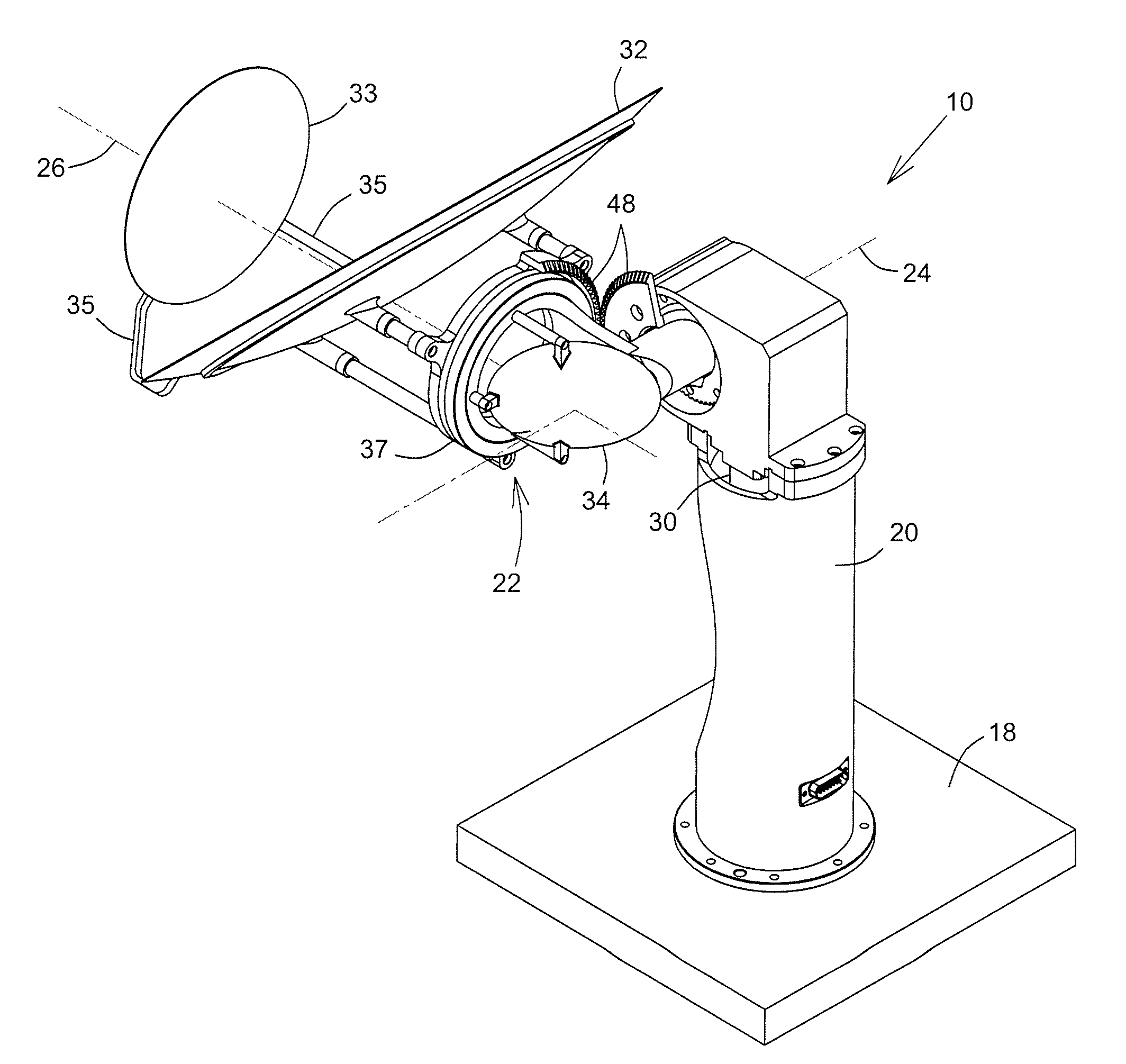
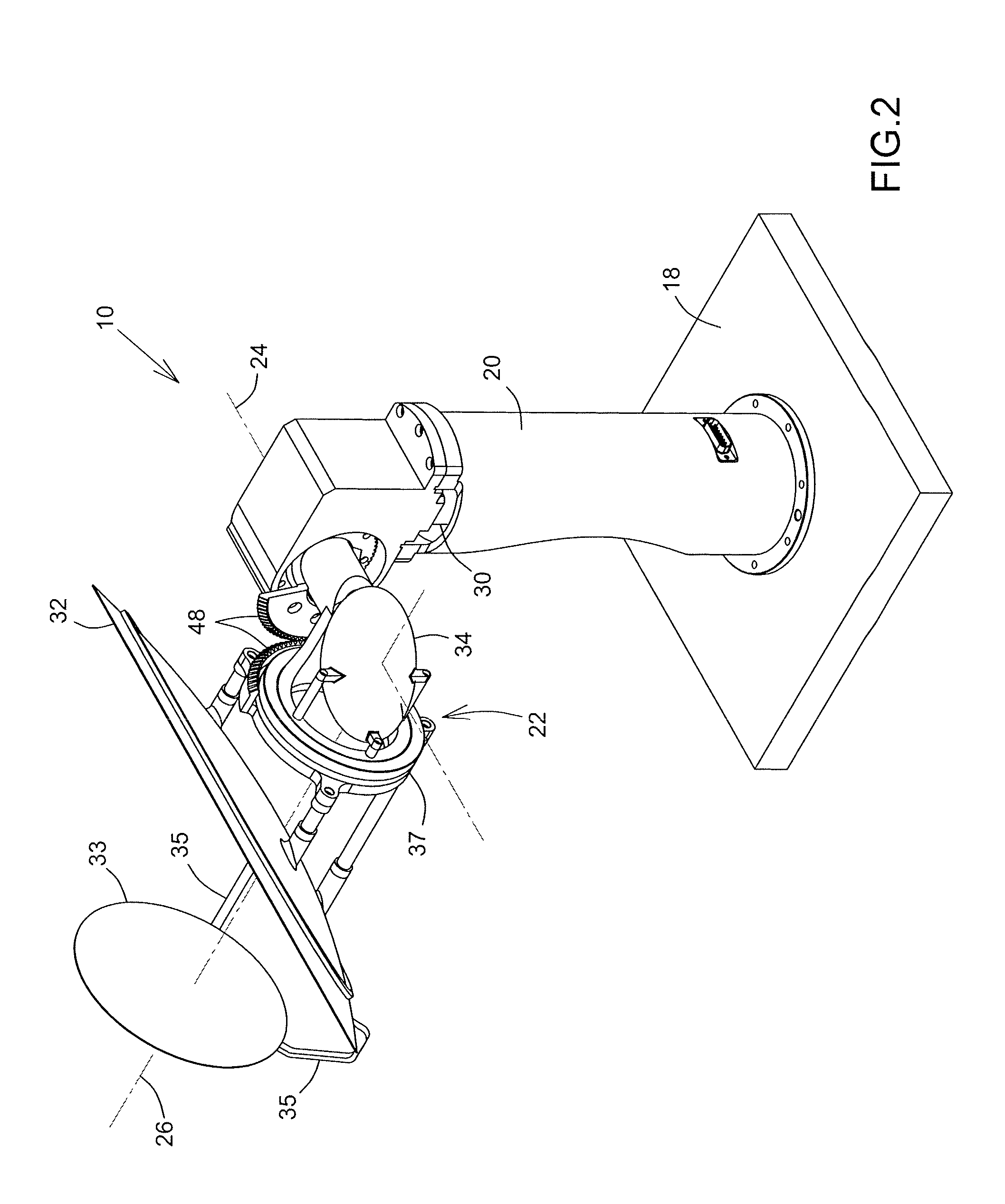
[0046]Referring to FIGS. 2 through 6, there is shown a steerable antenna 10 for allowing transmission and / or reception of an electromagnetic signal beam 12, typically over wide scan angles within an antenna coverage region, over a predetermined surface, such as the surface of the Earth when the antenna 10 is located on a spacecraft and / or satellite. The electromagnetic signal S travels through a feed chain 14 and between a feed source 16 and a target (not shown). The target moves within the antenna coverage region in which the antenna signal beam 12 is to be steered.

[0047]The antenna 10 includes a support structure 20 (or pedestal) for attaching to a base 18, such as a spacecraft panel or the like. The support structure 20 defines a stationary (non-moving) side of the antenna 10. A transmitting and / or re...


PUM


Abstract

A steerable antenna configuration having all actuators and the feed source mounted on a stationary side of the antenna thereby eliminating the need of having to supply power and/or communication signal through, a rotation mechanism. A first actuator rotates a reflector assembly about a first axis, and a second actuator rotates at least a main reflector of the reflector assembly about a second axis perpendicular to the first axis. The second axis is rotatable about the first axis via the first actuator.

Description

CROSS-REFERENCE TO RELATED APPLICATIONS[0001]This application claims priority of U.S. Provisional Application for Patent No. 62 / 048,302 filed Sep. 10, 2014, the content of which is incorporated herein by reference in its entirety.FIELD OF THE INVENTION[0002]The present invention relates to the field of antenna systems, and is more particularly concerned with steerable antennas for transmitting and / or receiving electromagnetic signals.BACKGROUND OF THE INVENTION[0003]It is well known in the art to use steerable (or tracking) antennas to communicate with a relatively moving target over a wide scan angle. Especially in the aerospace industry, such steerable antennas preferably need to have high gain, low mass, and high reliability. The antennas used in wide scan applications typically include two rotation axes requiring two rotary joints, cable cassettes or other means of propagating the signal over each of the rotation axis. The elimination or the reduction of the number of RF (radio-...

Claims


Application Information

Patent Timeline
IPC IPC(8): H01Q3/20
CPCH01Q3/20H01Q3/08H01Q3/16H01Q19/134H01Q19/191
Inventor LANCIAULT, FRANCOISLOISELLE, PHILIPPEHORTH, RICHARDDARNEL, ERICRIEL, MATHIEU
Owner MACDONALD DETTWILER & ASSOC CORP
Why Eureka
Try Eureka