
Communication apparatus, communication system and communication method

a communication system and communication device technology, applied in the field of communication technologies, can solve the problems of large bandwidth, difficult to locate such a large bandwidth, and difficulty in hardware design of base stations and terminals, and achieve the effects of reducing the number of searches, saving physical control channel resources, and improving communication performan

Active Publication Date: 2016-03-10
SONY CORP
View PDF18 Cites 3 Cited by
  • Summary
  • Abstract
  • Description
  • Claims
  • Application Information

AI Technical Summary

Benefits of technology

The present patent is about a communication system and method that can improve communication performance. It can save physical control channel resources, reduce blind decoding searches, lower the complexity of user equipment, improve communication efficiency, and save power utilization efficiency in communication. The system can also improve communication performance by grouping scheduled carriers based on the likelihood of different scheduled carriers having the same or similar downlink control information.

Problems solved by technology

In order to satisfy the peak rate requirement, the LTE-A currently supports a bandwidth of 100 MHz, but it may be difficult to locate such a large bandwidth among existing available spectrum resources and such large bandwidth brings great difficulty to the hardware design of a base station and a terminal.
Thus in cross-carrier scheduling, DCI information carried in the PDCCH of the scheduling carrier may be more complex (including both the DCI of the scheduling carrier and DCI of all the scheduled carriers).
Apparently in the case of cross-carrier scheduling, the UE has to detect blindly in a search space with an increase in complexity, and a larger control channel resource may be required to satisfy the demand.

Method used


Image

  • Communication apparatus, communication system and communication method
  • Communication apparatus, communication system and communication method
  • Communication apparatus, communication system and communication method

Examples


first embodiment

1. the Present Disclosure (Applicable to Communication Resources at Different Frequencies)

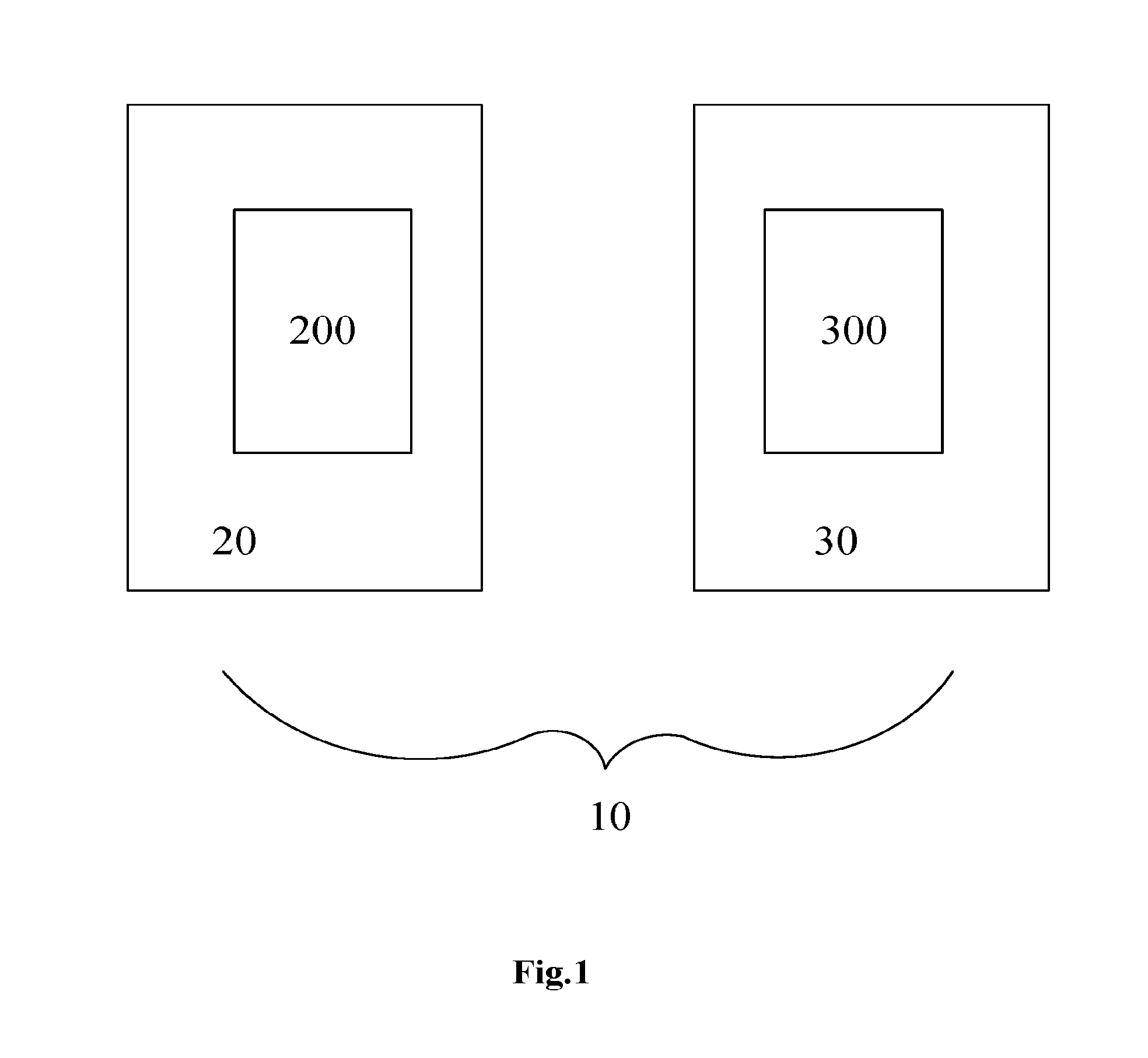
[0031]A communication apparatus according to the first embodiment of the present disclosure will be described below with reference to FIG. 1 to FIG. 4. In this embodiment, an aggregating object is carriers at different frequencies. In this embodiment, a conventional carrier operates as a scheduling carrier to schedule an NCT. Typically the scheduling carrier is a primary carrier, but those ordinarily skilled in the art shall appreciate that the scheduling carrier can alternatively be a secondary carrier, and correspondingly a scheduled carrier can alternatively be a secondary carrier.

[0032]In this embodiment, a legacy carrier operates as a scheduling carrier to schedule a New Carrier Type (NCT). Those ordinarily skilled in the art shall further appreciate that a scheduled carrier can alternatively be a conventional carrier instead of an NCT. The NCT will be introduced briefly below.

[0033]In ord...

second embodiment

2. the Present Disclosure (Applicable to Communication Resources at Different Transmission Time)

[0065]Although aggregation and scheduling of carriers has been described above, sub-frames can also be aggregated and scheduled in the time domain in the field of communication. Particularly a scheduling sub-frame sent from the base station side carries control information related to respective sub-frames, and the user equipment side receives the control information in the scheduling sub-frame and processes the respective sub-frames based upon the control information.

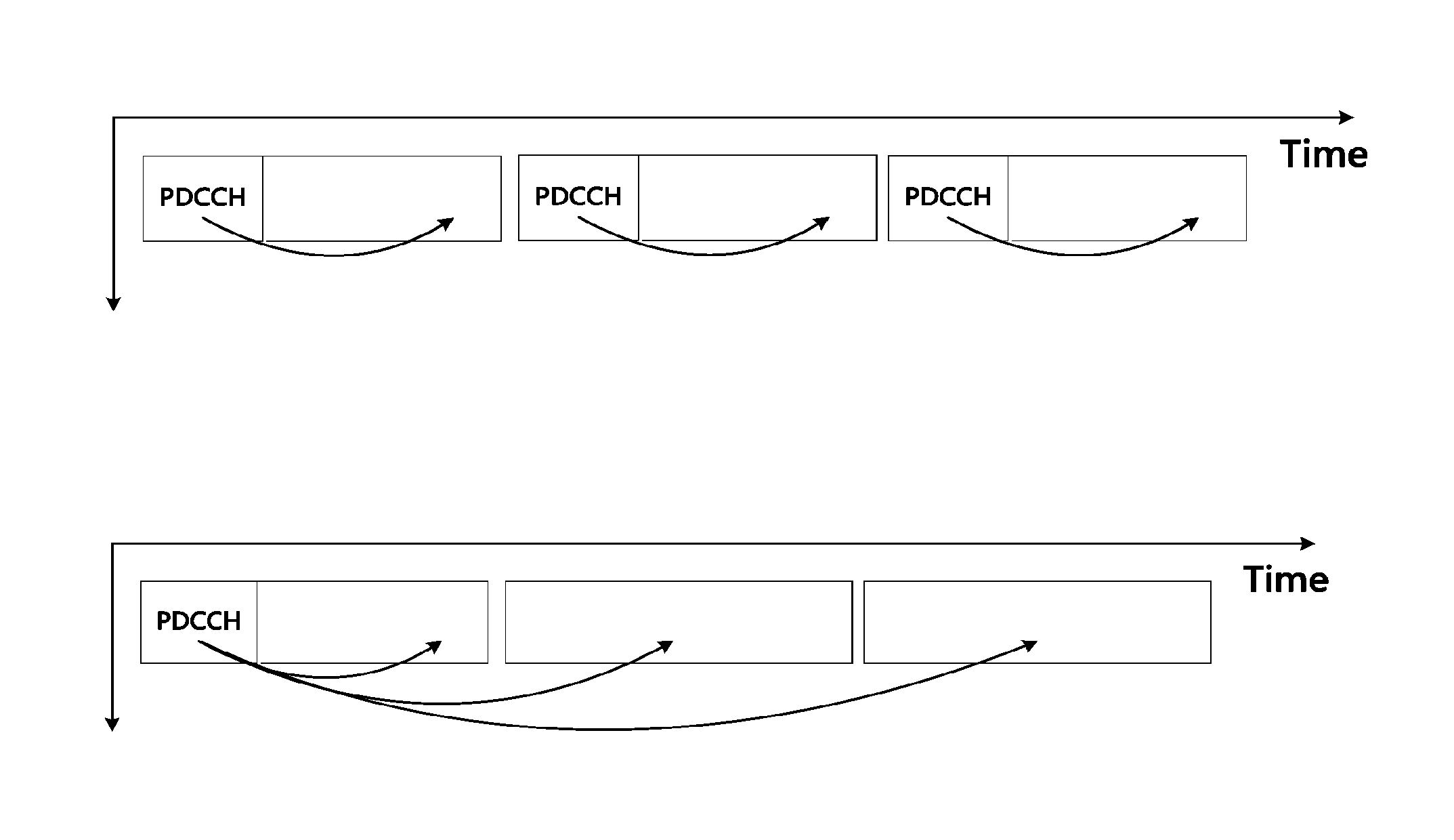
[0066]As a more particular example, as illustrated in FIG. 11, three downlink sub-frames originally having PDCCHs respectively (the upper half of FIG. 11) can be sent as follows: there is a PDCCH only in the first sub-frame, and DIC about all the three sub-frames is carried over the PDCCH (the lower half of FIG. 11). Upon reception of these three sub-frames at the user equipment side, the user equipment side obtains the infor...

third embodiment

3. the Present Disclosure (Applicable to Communication Resources at Both Different Frequencies and Transmission Time)

[0093]A communication apparatus according to the third embodiment of the present discourse will be described below. In this embodiment, an aggregating object is sub-frames at both different transmission time and different frequencies for the carriers.

[0094]In other words, aggregation and scheduling in the frequency domain according to the first embodiment is extended to aggregation and scheduling in the frequency and time domains.

[0095]For a communication apparatus, communication system and method according to the third embodiment of the present disclosure, reference can be made to FIG. 5 to FIG. 8 in which the communication apparatus, communication system and method according to the second embodiment of the present disclosure have been described.

[0096]An aggregation and scheduling object according to the third embodiment of the present disclosure is sub-frames as the...


PUM


Abstract

A communication apparatus, communication system and communication method. The related communication apparatus is used for aggregating, at a base station side, communication resources at different frequencies and / or different transmission time, wherein a scheduling resource among the aggregated communication resources is used for transmitting control information about the scheduling resource and scheduled resources. The communication apparatus includes: a grouping unit configured to divide the communication resources into groups based on characteristics of the communication resources, wherein the same group of the communication resource is indicated by the same piece of control information; and a sending unit configured to send the control information to a corresponding communication terminal side by the scheduling resource. The communication apparatus, communication system and communication method improve communication performance.

Description

FIELD OF THE INVENTION[0001]The present disclosure relates to the field of communication technologies, particularly to a communication apparatus, communication system and communication method and more particularly to a communication apparatus, communication system and communication method for aggregating communication resources at different frequencies and / or different transmission time.BACKGROUND OF THE INVENTION[0002]The Long Term Evolution (LTE) of the Universal Mobile Telecommunication System (UMTS) technology has been a major new technology research and development item initiated by the 3rd Generation Partnership Project (3GPP) in recent years. This technology can be regarded as a “quasi-4G technology”. The LTE-Advanced (LTE-A) has been subsequent evolvement of the LTE. The 3GPP finalized the technical demand report of the LTE-A in 2008 and proposed the lowest demands of the LTE-A: a downlink peak rate of 1 Gbps and an uplink peak rate of 500 Mbps with spectrum utilization rati...

Claims


Application Information

Patent Timeline
Patent Type & Authority Applications(United States)
IPC IPC(8): H04W72/12H04L5/00H04L5/06H04W72/04
CPCH04W72/12H04W72/0406H04W88/08H04L5/06H04L5/0057H04W72/0446H04W72/00H04L5/001H04W72/23H04W72/20
Inventor CUI, QIMEIZENG, LIANGHAN, JIANGZHANG, YINGNICHEN, NINGYU
Owner SONY CORP
Learn More