Imaging a patient's interior

a technology for a patient, applied in the field of imaging a patient's interior, to achieve the effect of less complex system or method

Active Publication Date: 2016-03-17
KONINKLJIJKE PHILIPS NV
View PDF7 Cites 20 Cited by
  • Summary
  • Abstract
  • Description
  • Claims
  • Application Information

AI Technical Summary

Benefits of technology

[0011]It would be advantageous to have a less complex system or method for est

Problems solved by technology

A problem of the imaging system of US 2010/0149315 A1 is that it is complex as it requires the use of different types

Method used


Image

  • Imaging a patient's interior
  • Imaging a patient's interior
  • Imaging a patient's interior

Examples


Embodiment Construction

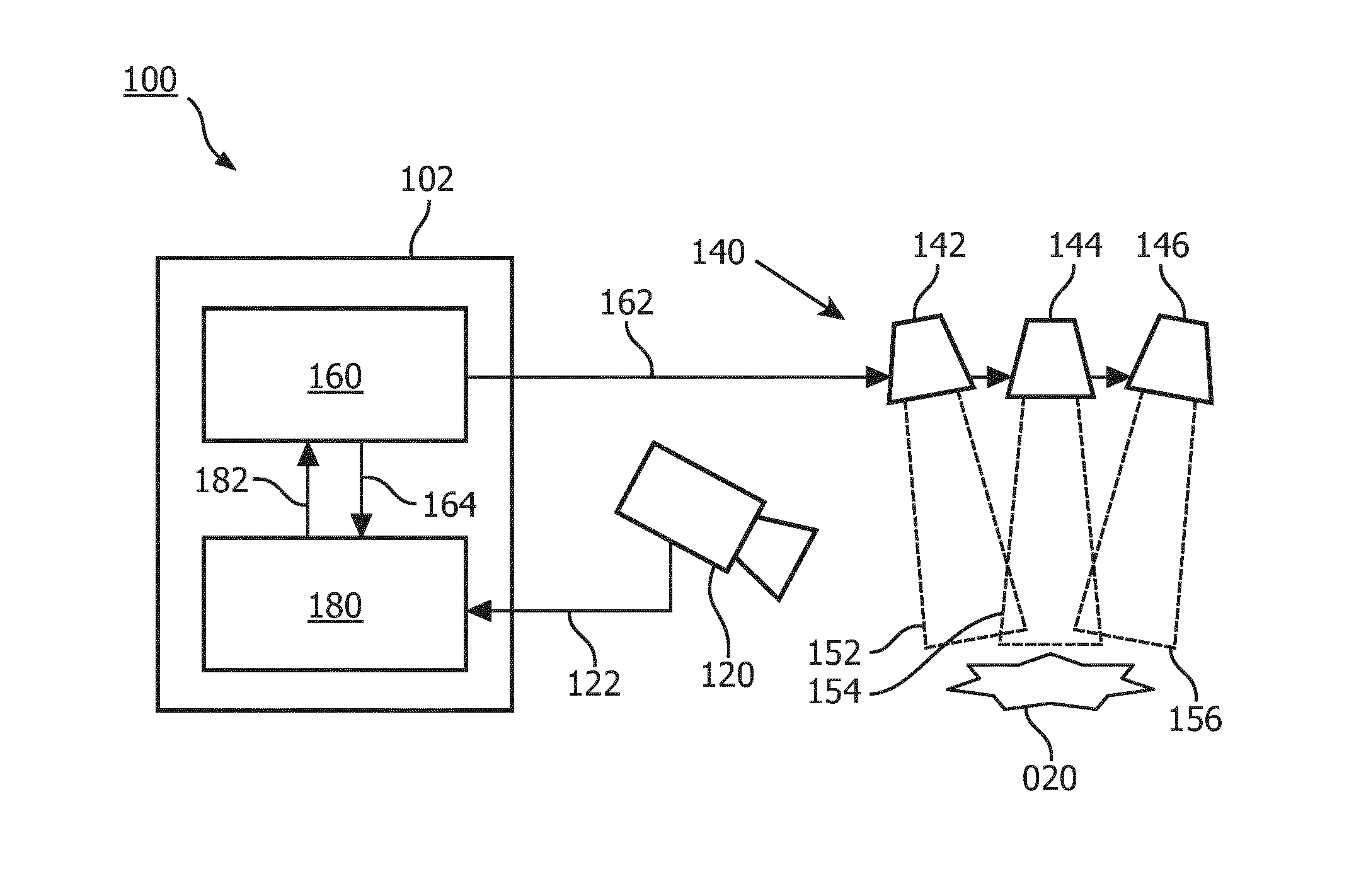
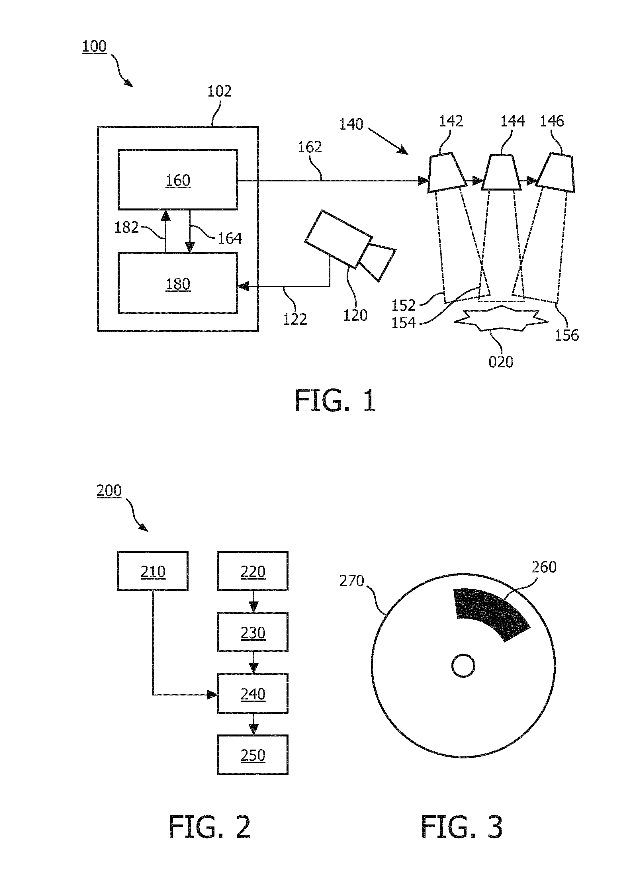
[0055]FIG. 1 shows a system 100 for imaging a patient's interior. The system 100 comprises an imaging sensor 120 for acquiring, in the form of image data 122, a series of images of a region of interest 020 in the patient's interior. For illustration purposes, the region of interest 020 is shown schematically in FIG. 1 by means of a star-shaped region, without showing the patient's interior nor the patient itself. It will be appreciated that during actual use of the system 100, the imaging sensor 120 will be positioned such that it is directed at a region of interest in the patient's interior, e.g., by being inserted into the patient's interior, directed at an opening in the patient's interior, etc. The system 100 further comprises a plurality of light sources 140 for illuminating the region of interest 020 in the patient's interior from different light source directions 152-156. By way of example, FIG. 1 shows the plurality of light sources 140 being comprised of a first light sourc...


PUM


Abstract

A system (100) is provided for imaging a patient's interior. The system comprises an imaging sensor (120) for acquiring a series of images of a region of interest (020) in the patient's interior, and a plurality of light sources (140) for illuminating the region of interest in the patient's interior from different light source directions (152-156). A light controller (160) is provided for controlling individual ones (142-146) of the plurality of light sources (140) to dynamically vary the light source directions (152-156) during said acquiring. Moreover, a processor (180) is provided for obtaining lighting data (164) indicative of the dynamically varying light source directions. The processor (180) is further arranged for using the lighting data to apply a photometric stereo technique to the image data so as to establish a three-dimensional [3D] surface profile of the region of interest. The processor (180) is further provided to detect insufficiently illuminated areas of the region of interest (020-024) in the images acquired by the imaging sensor (120), using the 3D surface profile of the region of interest. Accordingly, the system is enabled to establish a 3D surface profile of the region of interest from a series of images in a convenient and cost-effective manner.

Description

FIELD OF THE INVENTION[0001]The invention relates to a system and a method for imaging a patient's interior and a computer program product for causing a processor system to perform the method.[0002]Medical diagnosis frequently involves imaging of a patient's interior. For example, in the detection of cervical cancer, a clinician may examine a patient's cervix using a colposcope, i.e., a device which allows the clinician to grade precancerous and early invasive cervical cancer lesions and to identify locations to perform biopsies. A colposcope typically comprises an imaging sensor to acquire one or more images of a region of interest in the patient's interior, e.g., the cervix or part thereof. Moreover, such a colposcope typically comprises a light source to illuminate the region of interest while acquiring the images. As a result, the clinician is provided with images of the region of interest being illuminated.BACKGROUND OF THE INVENTION[0003]It is desirable to establish a three-di...

Claims


Application Information

Patent Timeline
IPC IPC(8): A61B1/00A61B1/04A61B1/06A61B1/303A61B1/313A61B3/12G06T7/00H04N5/225H04N7/18
CPCA61B1/00006H04N7/183H04N5/2256G06T7/0073A61B1/04A61B1/0661G06T2207/30004A61B1/3132A61B3/12H04N2005/2255G06T2207/10021G06T2207/10068G06T2207/10152A61B1/303A61B1/0607G06T7/586A61B1/00194A61B1/0605A61B1/0627A61B1/0655A61B1/044H04N23/56H04N23/555
Inventor VENKATESAN, SHANKAR MOSURVAJINEPALLI, PALLAVIGUPTA, VIPINGOVINAHALLISATHYANARAYANA, SUSHANTHKULKARNI, MANDAR SHIRIKANT
Owner KONINKLJIJKE PHILIPS NV
Why Eureka
Try Eureka