
Radiographic device

a technology of radiographic devices and figs, applied in the direction of radiation generation arrangements, instruments, applications, etc., can solve the problems of figs at the joint of images, and achieve the effect of reducing excessive load

Inactive Publication Date: 2016-03-17
SHIMADZU CORP
View PDF6 Cites 4 Cited by
  • Summary
  • Abstract
  • Description
  • Claims
  • Application Information

AI Technical Summary

Benefits of technology

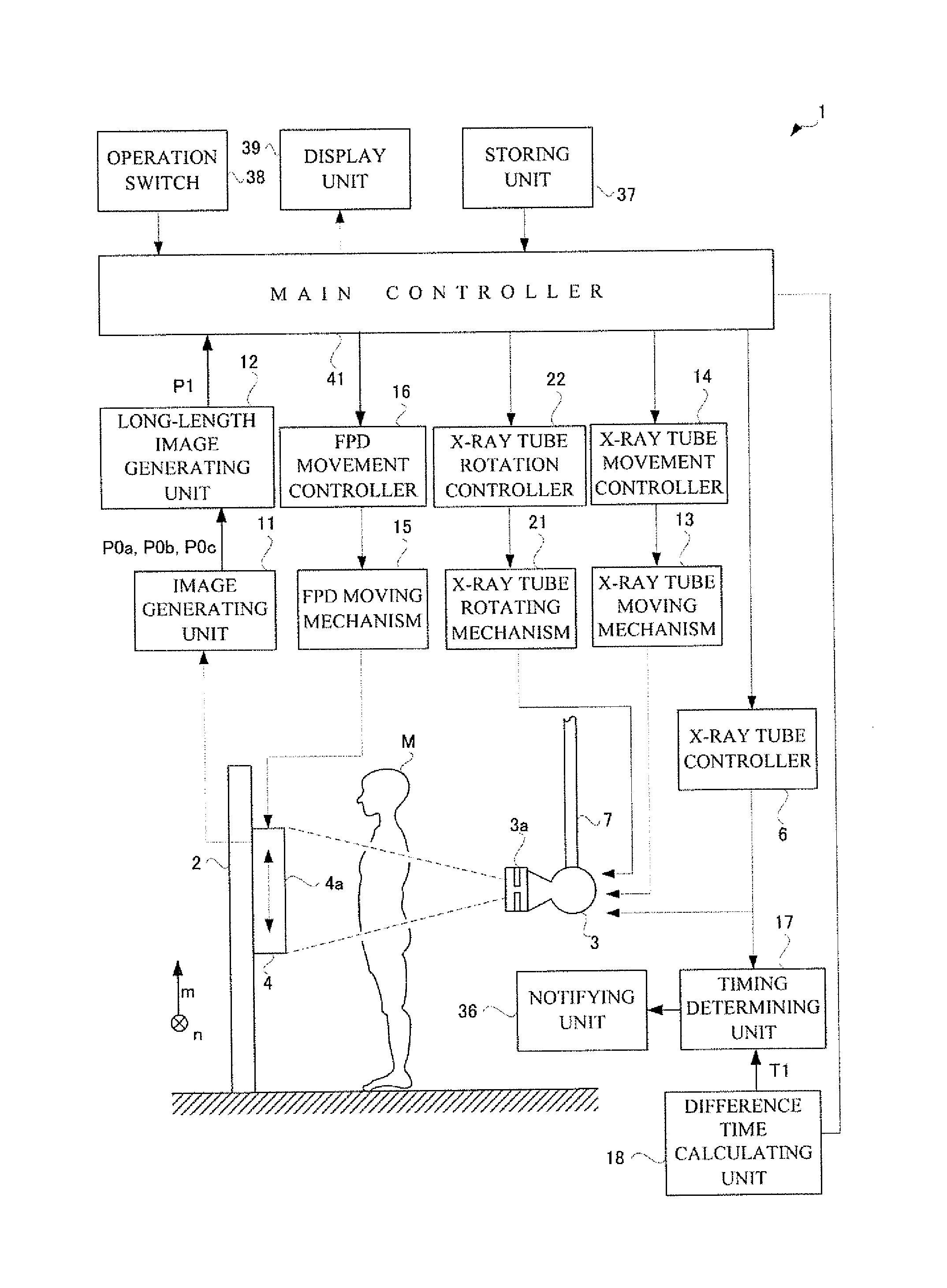
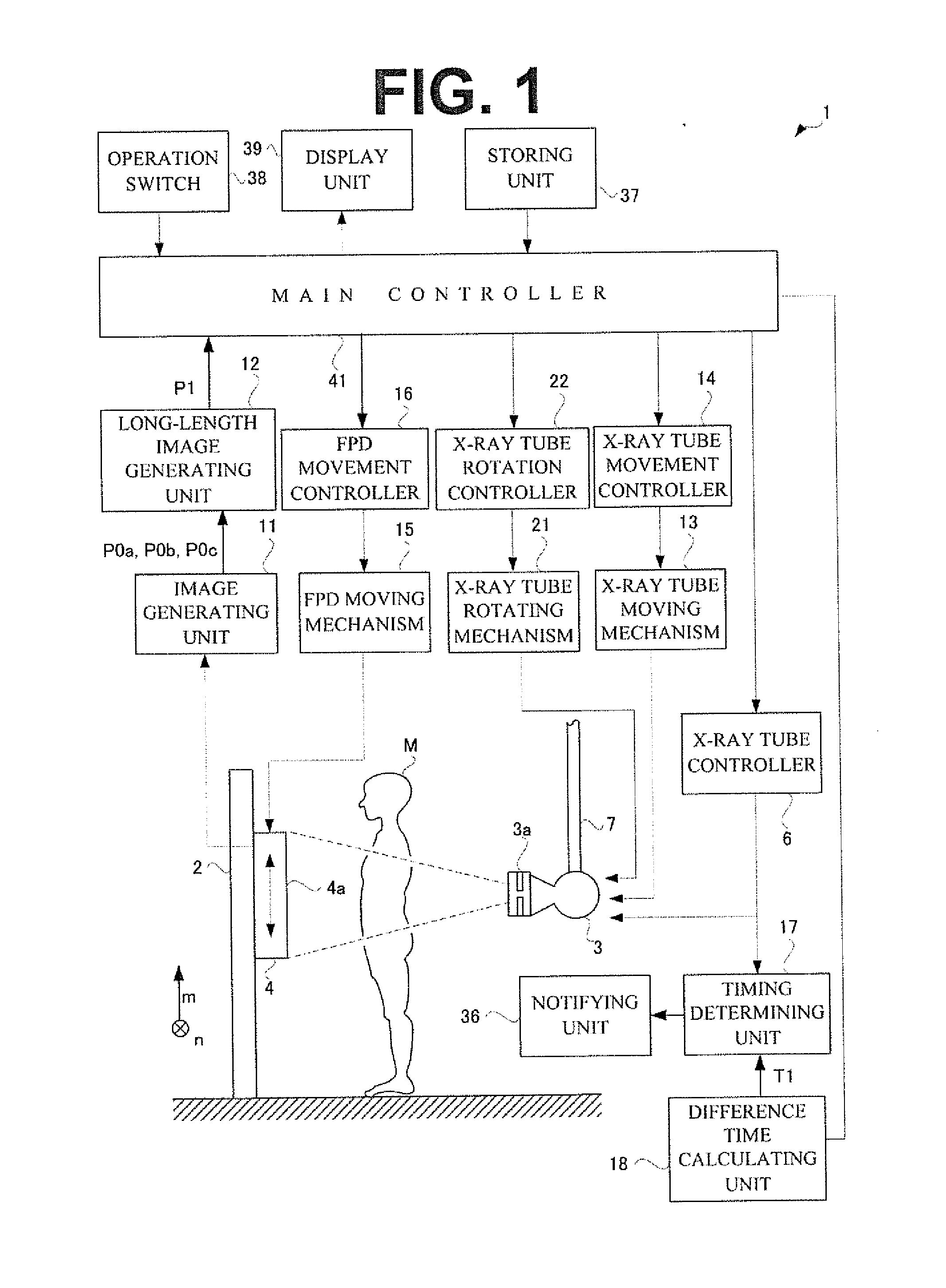
The radiographic apparatus of this patent uses a special technique to activate the radiation source at the right time, so that multiple images can be taken quickly without overloading the source. This allows for faster and more efficient imaging.

Problems solved by technology

That is because a longer time period between the adjacent imaging causes movement of the subject during the imaging, leading to a deviation of FIGs at a joint of the images.

Method used


Image

  • Radiographic device
  • Radiographic device
  • Radiographic device

Examples


embodiment 1

Effect of Embodiment 1

[0079]The following describes an effect by the timing determining unit 17 configured as mentioned above. FIG. 8 illustrates a conventional configuration. In the conventional configuration, an instruction to activate the X-ray tube 3 is displayed at time when the non-detectable time period of the FPD 4 ends. Accordingly, the operator activates the X-ray tube 3 after the non-detectable time period of the FPD 4 ends. The following is revealed from comparison between FIG. 8 and the upper of FIG. 4 illustrating Embodiment 1. That is, in Embodiment 1, the FPD 4 that does not allow detection of X-rays is restored simultaneously with the activation of the X-ray tube 3. In contrast to this, in the configuration illustrated in FIG. 8, the operations are performed in series. As noted above, Embodiment 1 achieves shorter time necessary for the posterior X-ray emission after the anterior X-ray emission than that in the conventional manual mode.

[0080]The following describes ...

embodiment 2

Effect of Embodiment 2

[0101]The following describes an effect by the timing determining unit 17 configured as mentioned above. FIG. 12 illustrates a conventional configuration. The following is revealed from comparison between FIG. 12 and FIG. 9(A) illustrating Embodiment 2. That is, in Embodiment 2, the X-ray tube 3 is in a rest state during X-ray emission. In contrast to this, in the conventional automatic mode in FIG. 12, the X-ray tube 3 is always in an activated state once the successive imaging is activated. Accordingly, in the conventional automatic mode, the filament in the X-ray tube 3 is always kept at high temperatures, causing ready damages on the filament. As noted above, Embodiment 1 achieves a longer life of the X-ray tube 3 than in the conventional type.

[0102]The other configuration of the X-ray apparatus 1 in Embodiment 2 is equal to that in Embodiment 1, and thus description thereof is to be omitted.

[0103]The following describes how the long-length radiography is a...


PUM


Abstract

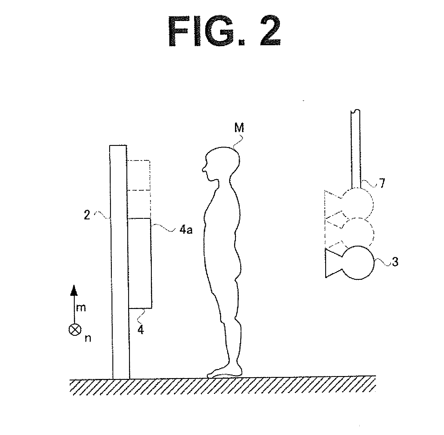
According to this radiography device, by taking images in rapid succession while appropriately obtaining the timing for which an X-ray tube in a rest state should be activated, rapid successive imaging and protection of a radioactive source can both be achieved. That is, in the configuration of the present invention, a time difference is calculated, obtained by subtracting a temporal width of an activation period from a temporal width of an undetectable period, and the time after the time difference has elapsed from the time at which an X-ray is irradiated is determined as the timing for activating the X-ray tube. The temporal width of an undetectable period is the temporal width between the time at which an FPD detects an X-ray once and the time at which the following X-ray can be detected, and the temporal width of an activation period is the temporal width between the start of activation of the X-ray tube to the completion of activation. Thus, while simultaneously activating the X-ray tube and preparing the detector, images can be taken in rapid succession without excessive burden on the X-ray tube and the life of the X-ray tube can be extended.

Description

CROSS REFERENCE TO RELATED APPLICATIONS[0001]This application is the U.S. National Phase under 35 U.S.C. §371, of International Application No. PCT / JP2013 / 000013, filed on Jan. 8, 2013, the disclosures of which is incorporated fully by reference.FIGURE SELECTED FOR PUBLICATION[0002]FIG. 1BACKGROUND OF THE INVENTION[0003]1. Technical Field[0004]The present invention relates to a radiographic apparatus that emits radiation to a subject to take a fluoroscopic image. More particularly, the present invention is directed to a radiographic apparatus that allows plural-time imaging successively.[0005]2. Background Art[0006]A medical institution is equipped with a radiographic apparatus that emits radiation to image a subject M. See, for example, Patent Literature 1. Such a radiographic apparatus includes a radiation source 53 emitting radiation, and an FPD 54 detecting radiation, as illustrated in FIG. 13. The subject M stands between the radiation source 53 and the FPD 54.[0007]The radiogr...

Claims


Application Information

Patent Timeline
Patent Type & Authority Applications(United States)
IPC IPC(8): A61B6/00
CPCA61B6/486A61B6/40A61B6/461A61B6/5241A61B6/54A61B6/542
Inventor OKUNO, TOMOHARUFUJII, HIDEKI
Owner SHIMADZU CORP
Learn More