Ultrahigh frequency RFID (radio frequency identification) reader with sighting function

a radio frequency identification and ultrahigh frequency technology, applied in the field of ultrahigh frequency radio frequency identification (rfid) readers, can solve the problems of wasting power, affecting the overall operation of the device, and the degree of narrowing is more serious than the degree of narrowing, so as to save power consumption

Inactive Publication Date: 2016-03-17
MARSON TECH
View PDF2 Cites 5 Cited by
  • Summary
  • Abstract
  • Description
  • Claims
  • Application Information

AI Technical Summary

Benefits of technology

[0005]In view of the above problems and demands, the main object of the present invention is to provide an UHF RFID reader with sighting function, which not only can read RFID tag promptly and accurately but also can save power consumption.
[0006]In order to achieve above objects, the UHF RFID reader with sighting function of the present invention is formed by a RF antenna and a controller, the RF antenna being assembled at the front end of the controller. The physical appearance of the radio frequency antenna is formed with a sighting portion. When a user want to read a RFID tag at remote place by the UHF RFID reader with sighting function, user can aim the sighting portion of the RF antenna at the RFID tag to be read by visual mode such that the line of sight, the sighting portion and the RFID tag are aligned on a line. Then, the controller actuates the RF antenna to emit a radio wave. In this manner, the effect of rapid aiming and accurate sensing can be achieved so as to solve the problem of failing to promptly aim at RFID tag happened in conventional UHF RFID reader. Furthermore, the reading operation conducted after aiming at the RFID tag enables effective use of power so as to achieve power saving purpose.

Problems solved by technology

However, as the wave emitted by the RF antenna is a directional wave, the farther the wave away from the RF antenna is, the more serious the degree of narrowing it becomes.
Thus, if users cannot aim the RF antenna at a remote RFID tag 11 to be sensed, it often happens to have the cases of failure in sensing.
Therefore, it is very common that users has to change the position of UHF RFID reader 10 constantly in order to sight the RFID tag, this often causes great inconvenience during its overall operation.
Furthermore, in the process of transmitting and sensing radio waves repeatedly, the power of the UHF RFID reader 10 is rapidly consumed.

Method used


Image

  • Ultrahigh frequency RFID (radio frequency identification) reader with sighting function
  • Ultrahigh frequency RFID (radio frequency identification) reader with sighting function
  • Ultrahigh frequency RFID (radio frequency identification) reader with sighting function

Examples


Embodiment Construction

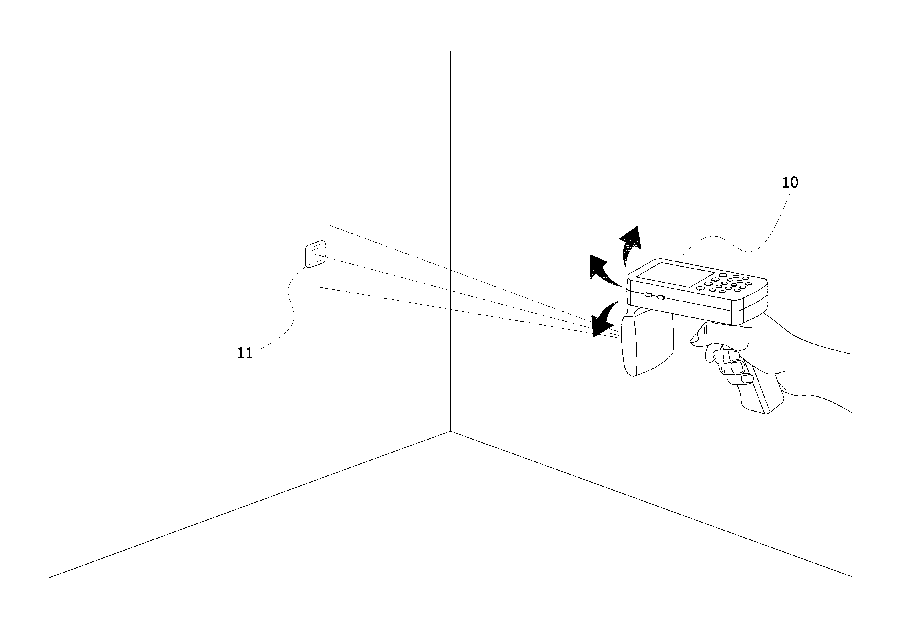
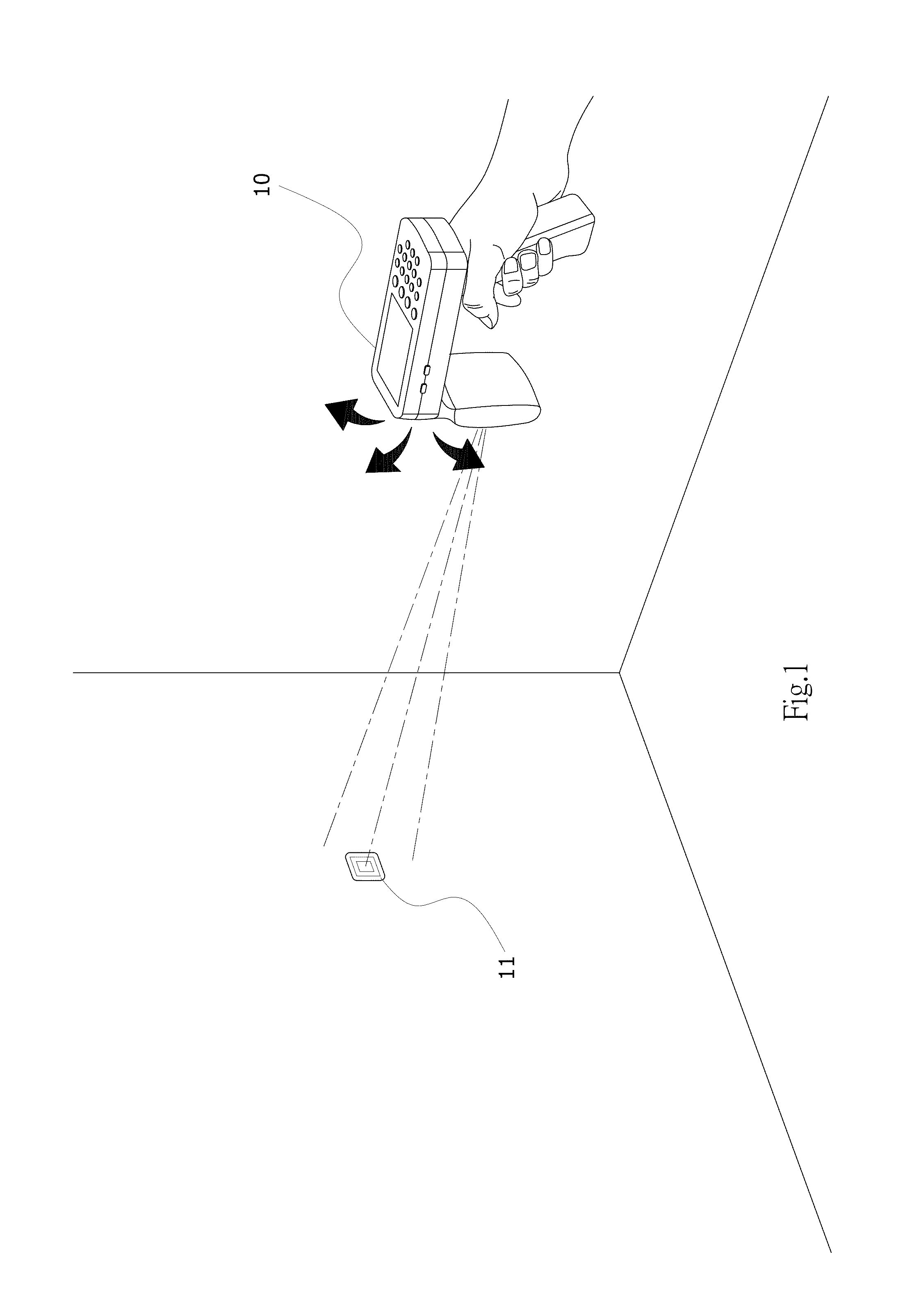
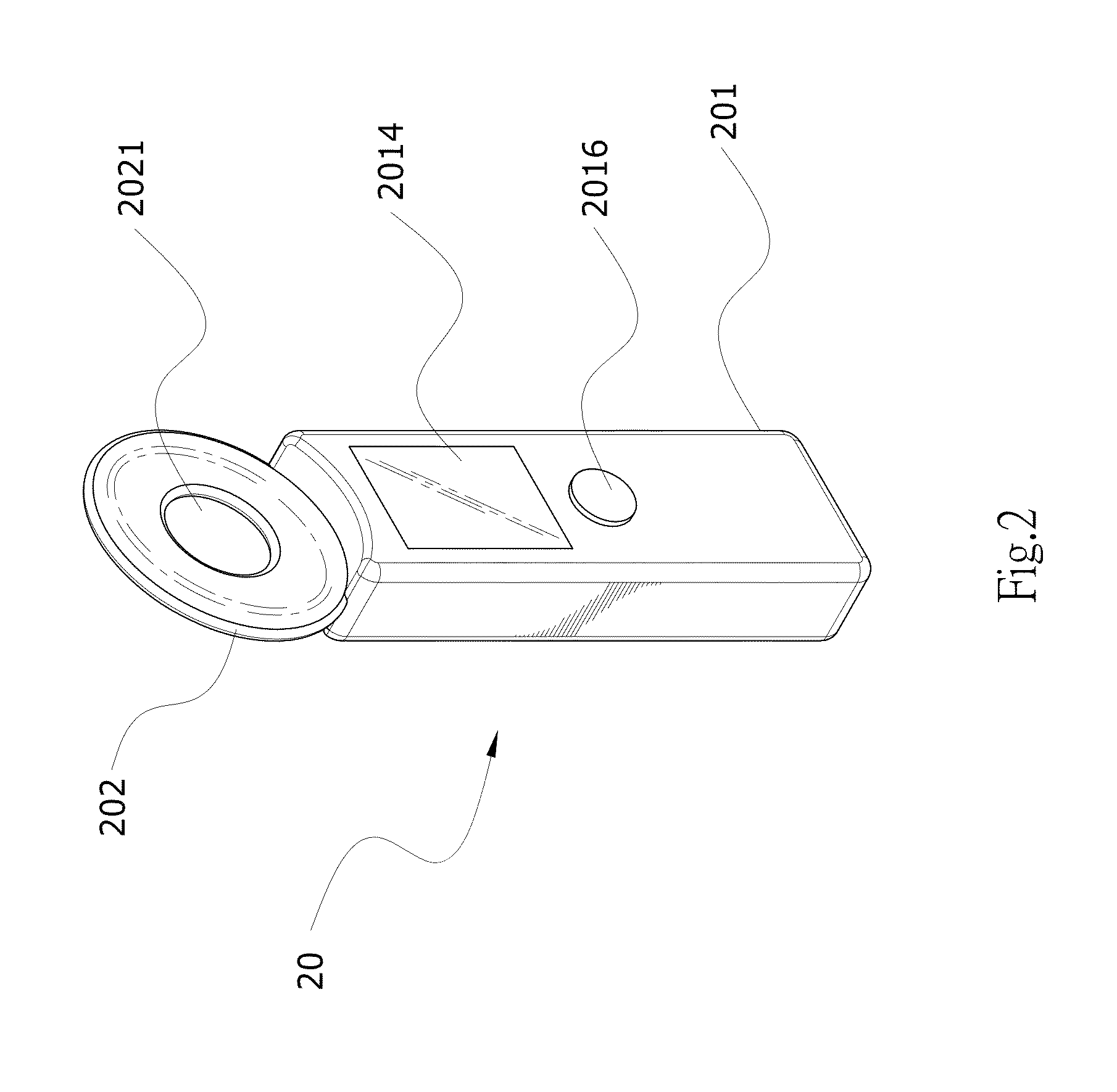
[0012]Referring to FIG. 2, a perspective view of the present invention, the UHF RFID reader 20 with sighting function of the present invention is mainly formed by a controller 201 and a RF antenna 202. On the physical appearance of the RF antenna 202, a sighting portion 2021 of through-hole shape is formed to have the function similar to a front sight of firearm. Alternatively, the sighting portion 2021 can also be formed as the other type such as a cross hole, a diamond hole, but is not limited to these. Further, the RF antenna 202 is assembled on one end of the controller 201 and is in electrical connection and in information linking to the controller 201. The controller 201 has a display screen 2014 and at least one operation key(s) 2016 by which users can operate so as to watch information displayed on the screen 2014. Therefore, when the controller 201 is operated by users, the RF antenna 202 is driven to emit a radio wave and to conduct sensing a RF tag at remote location. Fur...


PUM


Abstract

An ultrahigh frequency (UHF) radio frequency identification (RFID) reader with sighting function for reading RFID tag is mainly formed by a RF antenna and a controller, wherein the physical appearance of the RF antenna is formed with a sighting portion. In reading operation, users can aim the sighting portion of the RF antenna at a RFID tag at a remote location by visual mode so that the RF antenna can finish the reading operation promptly and accurately. Therefore, the reading accuracy and efficiency and power consumption can be improved.

Description

BACKGROUND OF INVENTION[0001]1. Field of the Invention[0002]The present invention relates to an ultrahigh frequency (UHF) radio frequency identification (RFID) reader, more particularly to an UHF RFID reader with sighting function, by which rapid aiming at RFID tag to be read can be achieved.[0003]2. Brief Description of Prior Art[0004]Radio frequency identification (RFID) is a technology widely used in contactless wireless communication. When in implementation, RFID is usually formed by at least one RFID reader and several RFID tags. As it has advantages of high data safety, reusability, good penetration, fast reading speed, it gradually replaces conventional bar code identification and largely used in our daily life, such as health care, logistic, personal authentication identification. FIG. 1 shows a conventional UHF RFID reader 10, the frequency band range of its RF antenna is within 865˜960 MHz and the effective sensing range is 1˜10 meters, the application of which is focus in...

Claims


Application Information

Patent Timeline
Patent Type & Authority Applications(United States)
IPC IPC(8): G06K7/10
CPCG06K7/10316G06K7/10792
Inventor LIOU, TING-FONG
Owner MARSON TECH
Why Eureka
Try Eureka