

System and methods for determining fuel fill level
- Summary
- Abstract
- Description
- Claims
- Application Information
AI Technical Summary
Benefits of technology
Problems solved by technology
Method used
Image


Examples
Embodiment Construction
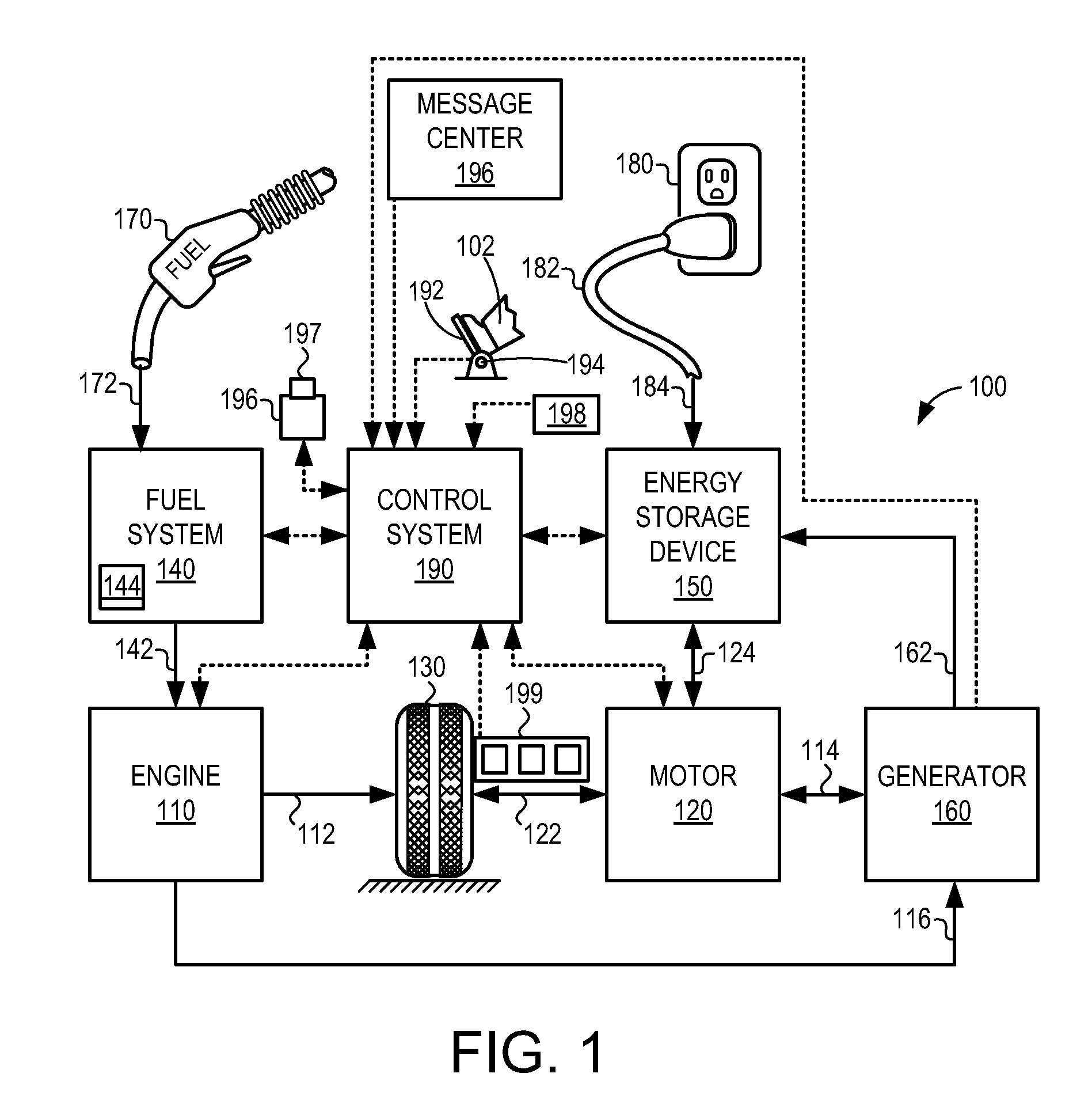
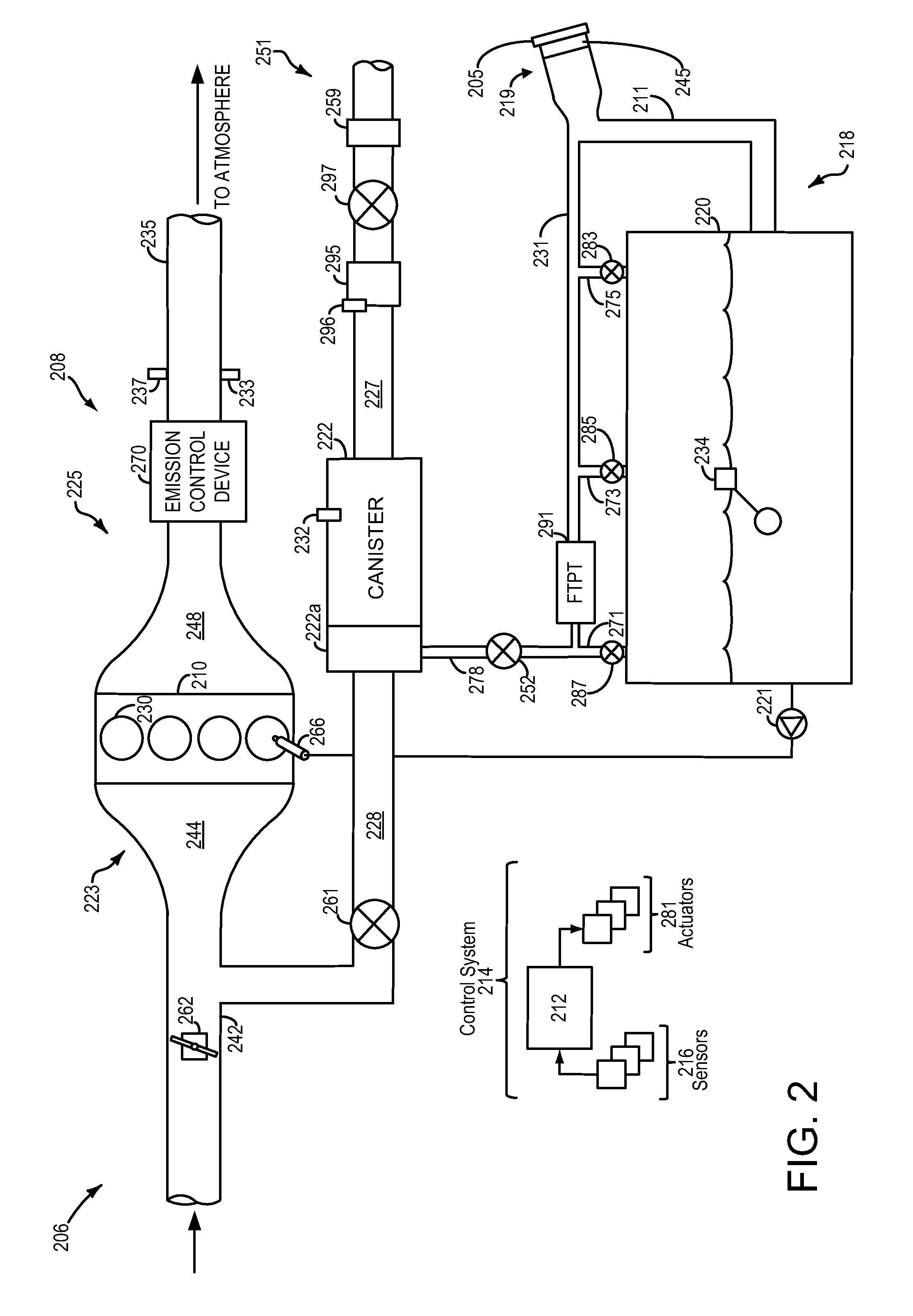
[0018]The following detailed description relates to systems and methods for determining a fuel fill level of a vehicle fuel tank. Specifically, the description entails means for using fuel tank pressure measurements during a refueling event as a basis for determining the amount of fuel added to the fuel tank. In some examples, the pressure measurements may also be used to diagnose degradation of a fill level indicator. A vehicle fuel tank may be included in a hybrid vehicle, such as the hybrid vehicle depicted in FIG. 1. The fuel tank may be comprised in a fuel system coupled to a vehicle engine as depicted in FIG. 2. The fuel tank may be coupled to a fill level indicator and a fuel tank pressure transducer. If a controller is maintained on during a refueling event, the outputs of the fuel level indicator and fuel tank pressure transducer may be monitored during the refueling event. FIG. 3A shows a timeline for an example refueling event. At the initiation of the refueling event, th...
PUM
 Abstract
Description
Claims
Application Information