
Fuel Blending Hose and Fuel Dispensing Unit

a technology of fuel blending hose and fuel dispensing unit, which is applied in the direction of liquid transferring device, liquid handling, packaging goods type, etc., can solve the problems of presenting a lower grade of fuel than required, limiting the design of the system, and complicating the system

Active Publication Date: 2016-03-24
DOVER FUELING SOLUTIONS UK LTD
View PDF6 Cites 2 Cited by
  • Summary
  • Abstract
  • Description
  • Claims
  • Application Information

AI Technical Summary

Benefits of technology

The present invention relates to an improvement in fuel hoses for dispensing different grades of fuel with minimal contamination. It provides a fuel hose with two different sections, where the first section has a larger diameter and includes two fuel lines, while the second section has a smaller diameter and is flexible for user-friendliness. The larger diameter of the first section allows for a satisfactory fuel flow rate. The two fuel lines may be arranged coaxially within the first section to save space. The overall effect of this invention is to provide a fuel hose that can deliver multiple grades of fuel with minimal contamination and is easy to use.

Problems solved by technology

A problem with these systems occurs when a single fuel outlet or fuel line dispenses multiple grades of fuel.
This contamination can often present a lower grade of fuel than required.
However, this can be disadvantageous for users who only dispense a small volume of fuel since the volume within the system creates a large variation on the grade of the fuel and places a design limitation on the system due to the small volume.
However, this can complicate the system and fail to give the user the expected grade of fuel when the highest grade has been selected or a small volume is desired.
A problem with such a hose is that it requires a large diameter which makes the hose inflexible.
Another problem is that since the fuel lines will have to be small in order to fit within the hose, the fuel flow rate in said fuel lines will be limited.
The fuel lines are separated in the first hose portion and the problem of contamination is therefore limited to the second hose portion.

Method used


Image

  • Fuel Blending Hose and Fuel Dispensing Unit
  • Fuel Blending Hose and Fuel Dispensing Unit

Examples


Embodiment Construction

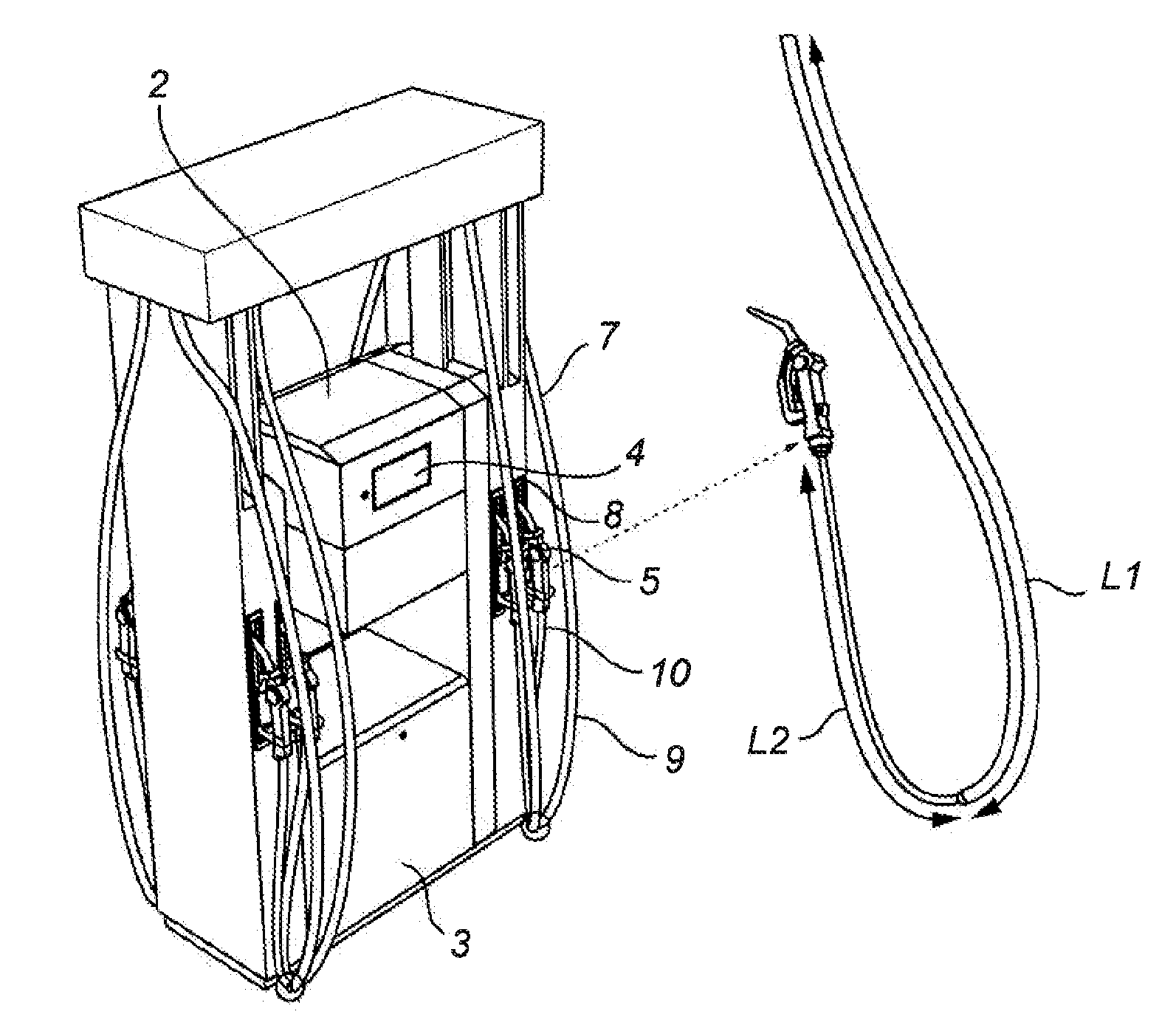
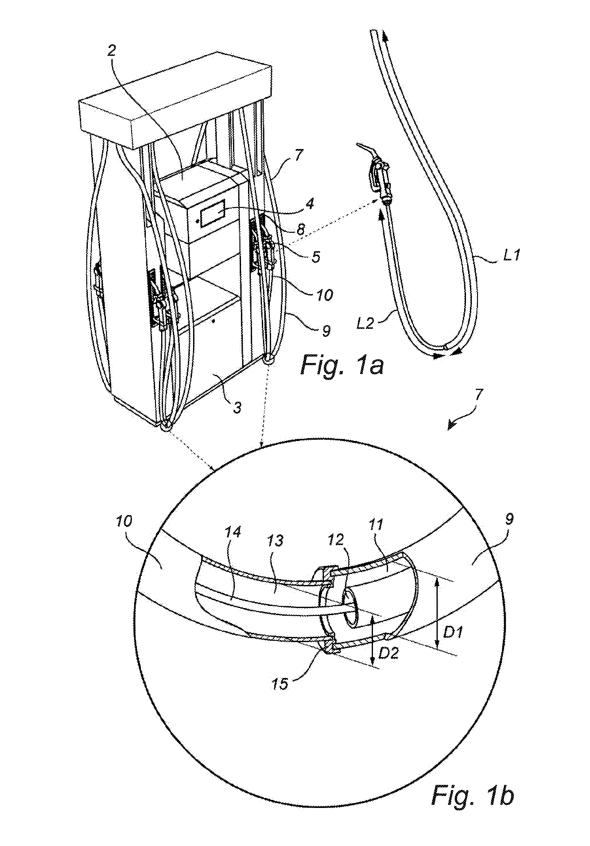
[0021]FIG. 1a illustrates a fuel dispensing unit 1 for refueling motor vehicles. The fuel dispensing unit 1 has an electrical cabinet 2 containing all the electronics for the fuel dispensing unit 1, a hydraulic cabinet 3 containing fuel dispensing means (not shown), e.g. fuel metering means, valves, vapor recovery system etc., a pump display 4 showing pump data, and a payment terminal (not shown). The fuel dispensing unit 1 is connected to an underground reservoir (not shown) containing fuel. When filling up the tank of a motor vehicle, the fuel is pumped from the underground reservoir by means of a pump (not shown) which is located in the hydraulic cabinet 3, and from there to a nozzle 5 via a fuel pipe (not shown) and a fuel hose 7. When filling-up does not take place, the fuel hose 7 hangs along the fuel dispensing unit 1, and the nozzle 5 is inserted in a nozzle boot 8.

[0022]In FIG. 1b, a section of the fuel hose 7 is illustrated in an enlarged view. The fuel hose 7 is adapted f...


PUM

PropertyMeasurementUnit
diameter D2aaaaaaaaaa
length L2aaaaaaaaaa

Abstract

A fuel hose for delivering multiple-grades of fuel is provided and in one embodiment includes a first hose portion having a first length and a first diameter, and a second hose portion having a second length and a second diameter. The first hose portion includes a first fuel line and a second fuel line, and the second hose portion includes a third fuel line. The first fuel line and the second fuel line can be fluidly connected to the third fuel line. In one embodiment, the first diameter of the first hose portion is larger than the second diameter of the second hose portion. The invention further relates to a fuel dispensing unit.

Description

CROSS-REFERENCE TO RELATED APPLICATIONS[0001]This application claims priority to Swedish Patent Application No. 1451099-4, filed on Sep. 18, 2014, which is hereby incorporated by reference in its entirety.FIELD[0002]The invention relates to a fuel hose for delivering multiple-grades of fuel, and a fuel dispensing unit having such a fuel hose.BACKGROUND ART[0003]Some fuel dispensing systems include multiple-grade fuel sources with single or multiple fuel outlets for dispensing various grades of fuel. Each fuel source may include a pump to dispense the fuel from its source to its respective meter for measuring the volume of fuel. The fuel then remains in its original concentration or it is blended with other fuels to form a separate concentration before reaching the fuel outlet. A problem with these systems occurs when a single fuel outlet or fuel line dispenses multiple grades of fuel. Lower grades of fuel can remain in the system while the user attempts to obtain a higher grade of f...

Claims


Application Information

Patent Timeline
Patent Type & Authority Applications(United States)
IPC IPC(8): B67D7/38B67D7/04B67D7/42B67D7/84F16L11/22
CPCB67D7/38B67D7/04F16L11/22B67D7/84B67D7/42B67D7/74B67D2007/746B67D2007/0425B67D2007/0426B01F25/3131B01F25/4334F16L11/20
Inventor LARSSON, BENGT, I.
Owner DOVER FUELING SOLUTIONS UK LTD
Learn More