Dual-head, pulseless peristaltic-type metering pump

a metering pump and peristaltic technology, applied in the direction of machines/engines, flexible member pumps, positive displacement liquid engines, etc., can solve the problems of high maintenance costs, non-steady flow or pulsation, and high wear of flexible tubes, so as to reduce the contamination of transferred materials, facilitate the setting up, and reduce the effect of metering costs

Active Publication Date: 2017-11-02
CHOI NELSON NAKSUN
View PDF9 Cites 1 Cited by
  • Summary
  • Abstract
  • Description
  • Claims
  • Application Information

AI Technical Summary

Benefits of technology

[0018]Peristaltic pumps are used to transfer liquids, gel, and semi-solids in many industries worldwide. These pumps have many advantages over other pumping methodologies such as they are easy to set up, and allow only minimal contamination of the transferred material. Existing peristaltic pump technology also has common problems: non-steady flow or flow pulsations, high degree of flexible tube wear, high maintenance cost and inaccurate metering. The pump design of the present invention addresses and minimizes these issues with a new housing and roller element design that uses new materials and a new design for the tube routing path. The roller element is manufactured with unique, non-metallic materials that increase pump efficiency and minimize tube wear. The tube layout minimizes pulsation and enables precise metering of pumped materials. A pump with a single head incorporating the invention of the present invention has considerably improved performance compared to the fluid pumps of the prior art. Furthermore, by placing two pump housings into one body installed with a 180 degree phase difference between each other, pulsation is compensated for and eliminated.

Problems solved by technology

Existing peristaltic pump technologies also have a common set of problems: non-steady flow or pulsations, high flexible tube wear, high maintenance costs and not highly accurate metering of pumped volumes.
This is the problem of pulsation that can damage fittings, piping and other system components connected at the output line.
This pinched area makes dose control difficult.
This results in the problem of shorter lifetime of hose sections.
In addition, friction between hose and roller is one of the factors that reduce lifetime of hose during operation.
In addition, metal cast rollers with high thermal conductivity can damage the hose by the heat of friction.
The amount of squeeze applied to the tubing affects pumping performance and the tube life—more squeezing decreases the tubing life dramatically, while less squeezing can cause the pumped medium to slip back, especially in high pressure pumping, and decreases the efficiency of the pump dramatically and the high velocity of the slip back typically causes premature failure of the hose.
However, a longer tube implies more pinch points between inlet and outlet, increasing the pressure that the pump can generate.
1. Existing rollers / shoes element scrub the transfer tube with forces that stretch the tube and require the tube to be anchored to the pump housing to keep it from migrating out of the pump head.
2. Existing rollers / shoes element design requires frequent lubrication due to friction. It causes friction and heat generation, eventually leading to maintenance and replacement.
3. Existing transfer a pulsation energy to the tube anchors and downstream components of the system that cause stress and eventual wear. This is caused by the pump occluding mechanism where the rollers / shoes element loses contact with the tube. This results in a pressure release. When the roller regains contact with the tube, a pressure increase occurs causing significant pulsing of the material flow and tubing vibration.
4. Tube stretching changes the inner diameter of the tube which changes the material volume through the tube. Periodically the pump must be calibrated to compensate for this varied tube shape.
This stretches the tube, and changes it's shape resulting in changed volume.
This is unacceptable in applications that require maintaining a constant volumetric flow rate.
In addition, many components are used in this complicated structure, giving rise to a higher potential for mechanical failure caused by wear.
Finally, a complicated design of drive assembly makes it difficult to replace tube that, increasing maintenance time and cost.
No US2012 / 0156074, the stator and rotor does not eliminate friction, therefore the use of hose clamps at the inlet and outlet prevent tube slippage.
Also this patent does not address the 3 pulsations by 3 rotors and wide pulsation between pump input hose and output hose.
However, a major drawback of this invention is that the complicated mechanism is created using many moving, wearable parts that increase the likelihood of potential mechanical failure and increase cost of maintenance.

Method used


Image

  • Dual-head, pulseless peristaltic-type metering pump
  • Dual-head, pulseless peristaltic-type metering pump
  • Dual-head, pulseless peristaltic-type metering pump

Examples


Embodiment Construction

[0042]The description that follows is presented to enable one skilled in the art to make and use the present invention, and is provided in the context of a particular application and its requirements. Various modifications to the disclosed embodiments will be apparent to those skilled in the art, and the general principals discussed below may be applied to other embodiments and applications without departing from the scope and spirit of the invention. Therefore, the invention is not intended to be limited to the embodiments disclosed, but the invention is to be given the largest possible scope which is consistent with the principals and features described herein.

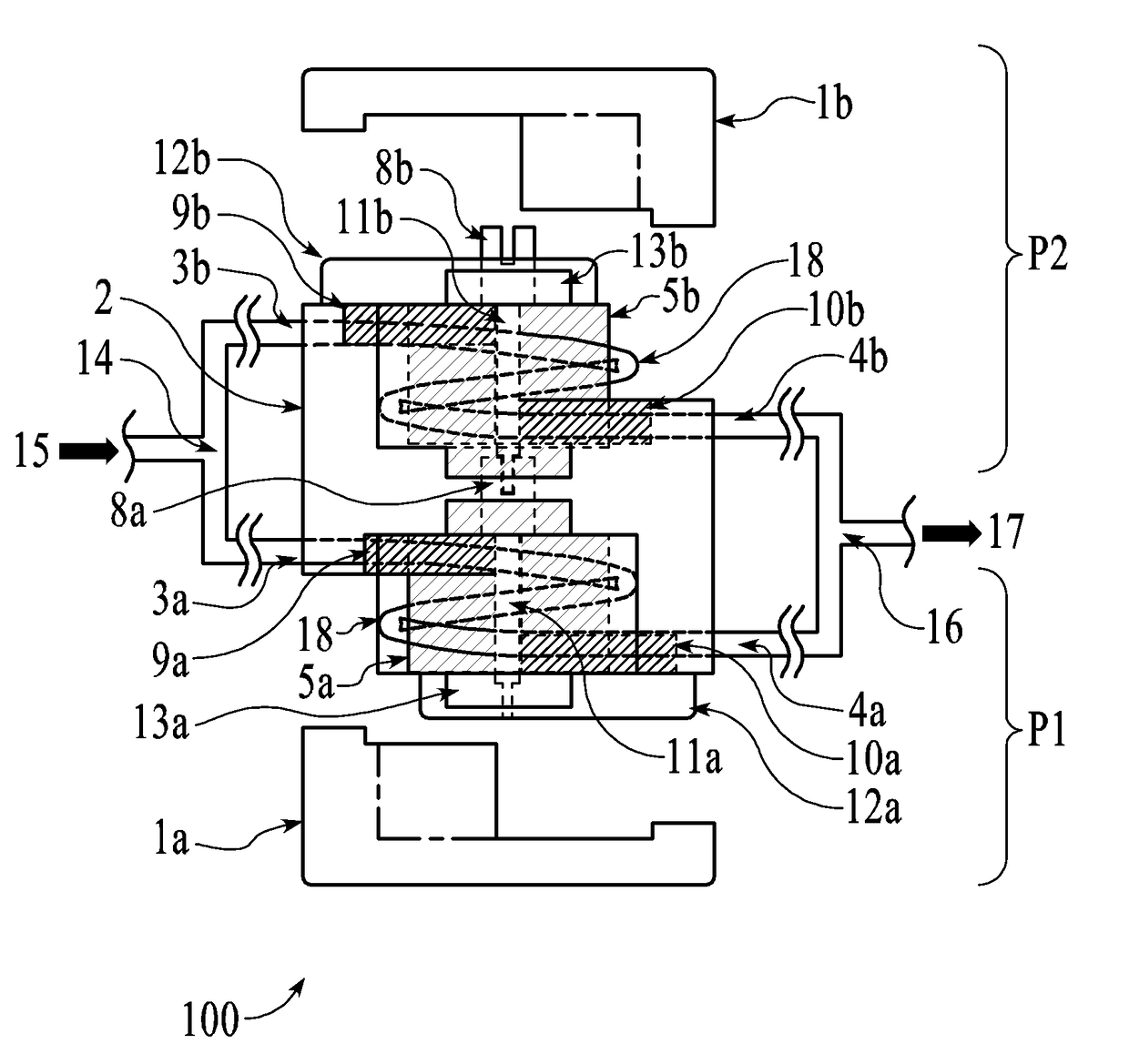
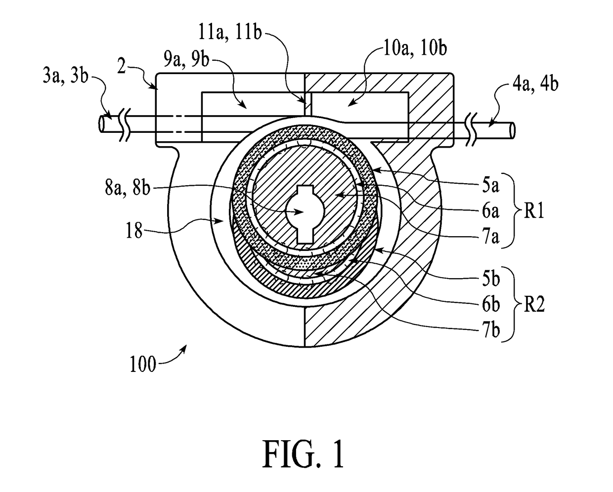
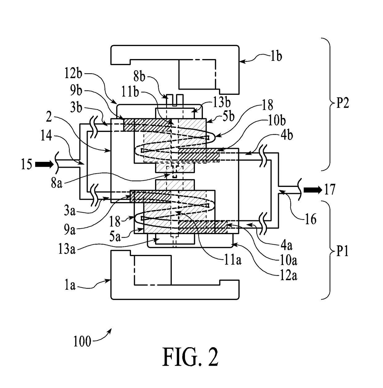
[0043]The following is a list of reference numerals and associated elements of the dual-head, pulseless peristaltic-type metering pump of the present invention.

[0044]1a, 1b Cover

[0045]2 Main body

[0046]3a, 3b Tube input

[0047]4a, 4b Tube output

[0048]5a, 5b Outer race roller element

[0049]6a, 6b Ball bearings or other roller ele...


PUM


Abstract

A dual-head, pulseless peristaltic-type pump comprises a pump housing, cover, two compressible tube chambers and two sets of rotatable occluding members. An off-center drive axis driven by motor or other rotational mechanism rotate inner large diameter disk. Balls or rollers between inner disk rotate in one direction from center drive axis where the outer ring is stationary and occludes the tube by linear motion without friction between tube and outer ring. The linear roller occluding motion transfers liquid or slurry from inlet to outlet of tube. In one embodiment, two separate sets of occluding members are installed 180 degree opposite to each other such that pulsations are compensated for and canceled out.

Description

RELATED APPLICATIONS[0001]NoneFIELD OF THE INVENTION[0002]The present invention is related to pulseless, positive displacement fluid / slurry / gas peristaltic pumps.BACKGROUND OF THE INVENTION[0003]Peristaltic pumps are used to transfer liquids, gel, and semi-solids in many industries worldwide. These pumps have many advantages over other pumping methodologies such as they are easy to setup, and allow minimal contamination of transferred materials. Peristaltic pumps operate by squeezing elastic tubing in one direction. The repeated discharge and vacuum of the fluid to be transferred moves the fluid.[0004]The peristaltic pump was designed to prevent contamination because no contact with the material being transferred is made with the exterior of the tubing. Existing peristaltic pump technologies also have a common set of problems: non-steady flow or pulsations, high flexible tube wear, high maintenance costs and not highly accurate metering of pumped volumes. The pump design of the pres...

Claims


Application Information

Patent Timeline
Patent Type & Authority Applications(United States)
IPC IPC(8): F04B43/12F04B43/00
CPCF04B43/1292F04B43/0072F04B43/1215F04B43/1238F04B43/1276
Inventor CHOI, NELSON NAKSUNCHOI, STEVE LIM
Owner CHOI NELSON NAKSUN
Why Eureka
Try Eureka