Safety Diagnosis System For Structure

Active Publication Date: 2016-03-24
KK TOPCON
View PDF3 Cites 8 Cited by
  • Summary
  • Abstract
  • Description
  • Claims
  • Application Information

AI Technical Summary

Benefits of technology

[0020]Further, according to the present invention, in the safety diagnosis system for structure, the diagnosis result screen further comprises an evaluation result display area for displaying a diagnosis result by the judging unit in letters and a comprehensive evaluation display area displaying the diagnosis result in color. As a result, the condition of the structure can be grasped immediately and a subsequent method of handling and the like can be grasped easily.
[0021]Further, according to the present invention, in the safety diagnosis system for structure, after the diagnosis of the structure is performed by the judging unit, and further, after a predetermined time has elapsed, the GNSS receiver measures an absolute coordinate of an installation position of the GNSS receiver, the control device calculates a displacement of the installation position over time from a reference absolute coordinate and the absolute coordinate of the installation position after the predetermined time has elapsed, and the judging unit diagnoses safety of the structure based on the displacement over time. As a result, a diagnosis of the structure including the aftereffect variation and a residual displacement of the structure can be performed, and an accuracy of safety diagnosis of the structure can be improved.
[0022]F

Problems solved by technology

However, in a case where an acceleration sensor is used, since a displacement amount of the structure cannot be directly collected as measurement data, it is necessary to obtain the displacement amount by applying the second-order integration to an acceleration data as acquired.
Therefore, the displacement amount of the structure needs to be acquired by calculation and consequently there is a problem that errors are accumula

Method used


Image

  • Safety Diagnosis System For Structure
  • Safety Diagnosis System For Structure
  • Safety Diagnosis System For Structure

Examples


Embodiment Construction

[0035]Description will be given below on embodiments of the present invention by referring to the attached drawings.

[0036]First, referring to FIG. 1 and FIG. 2, description will be given on general features of a safety diagnosis system for structure according to an embodiment of the present invention.

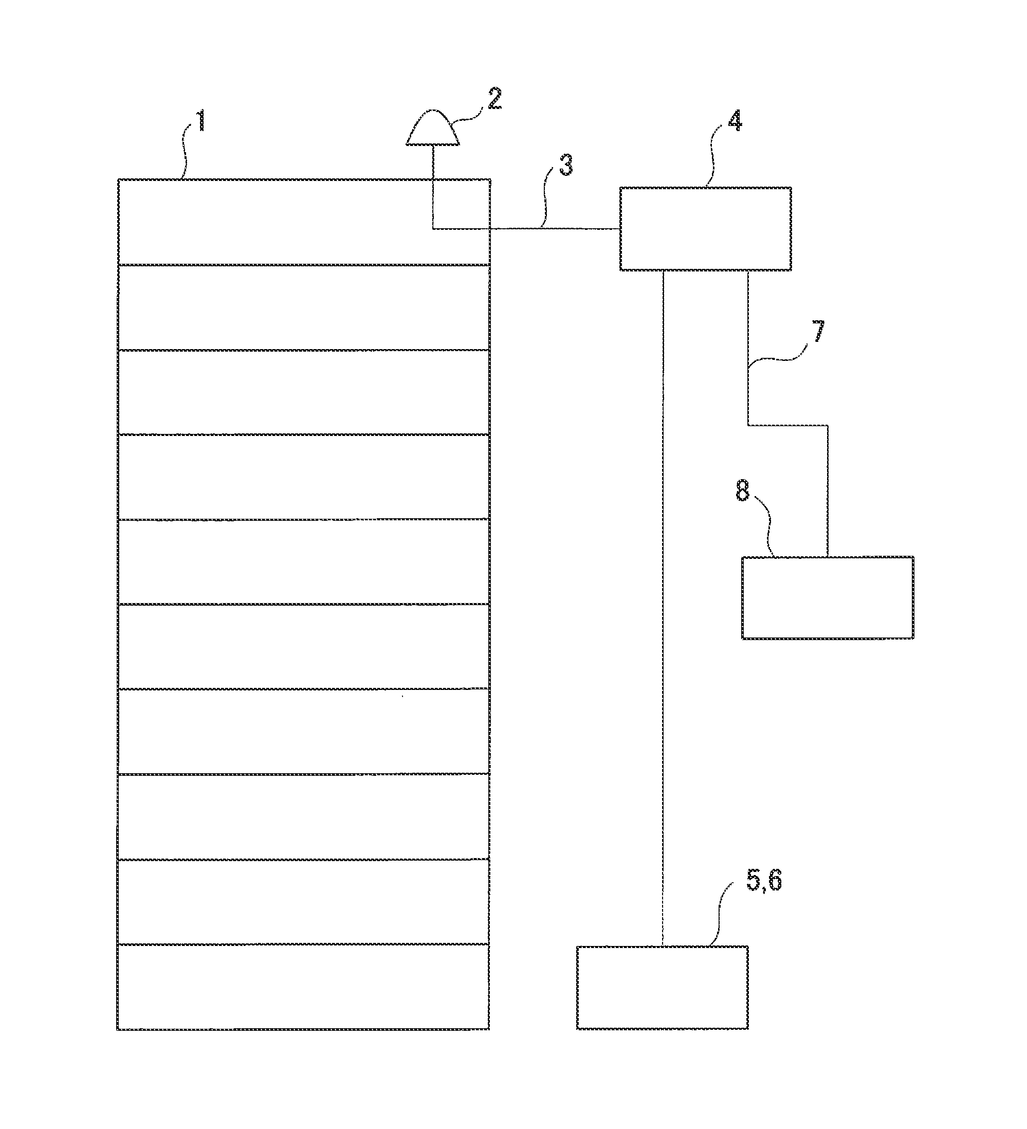
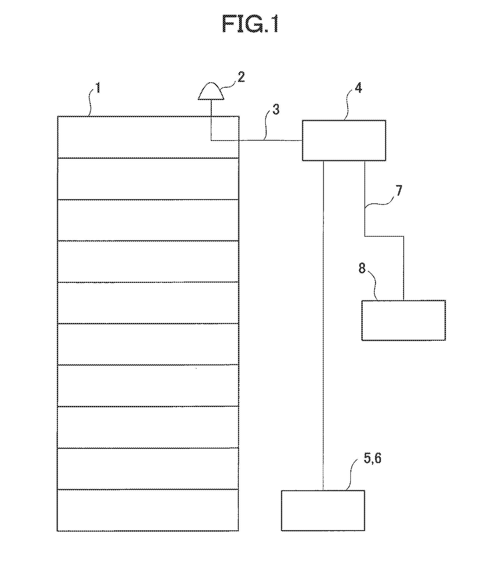
[0037]In FIG. 1, reference numeral 1 denotes a structure such as a building or the like and reference numeral 2 denotes a GNSS receiver provided at a predetermined position of an upper floor (preferably a known position on a rooftop floor) of the structure 1. When a GNSS receiving unit of the GNSS receiver 2 receives a signal from a plurality of satellites, the GNSS receiver 2 uses a Doppler fluctuation of each satellite as obtained and detects a displacement of an object from its fluctuation value. Further, the GNSS receiver 2 detects a vibration based on the displacement as detected.

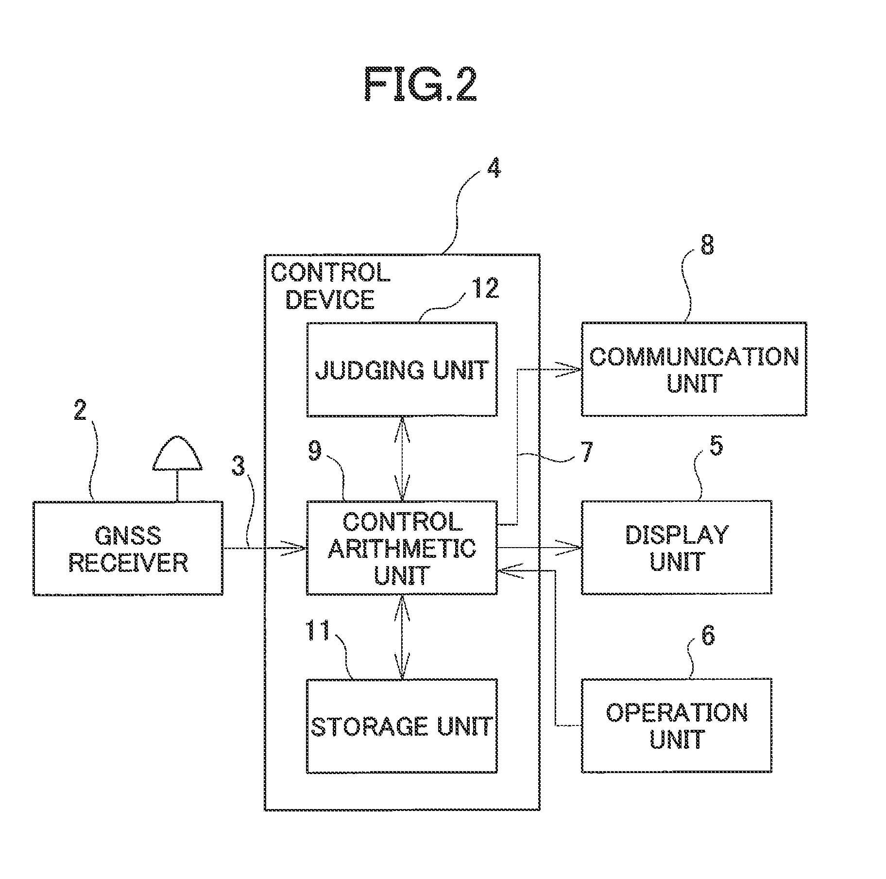
[0038]The GNSS receiver 2 is connected to a control device 4 such as a PC or the like via a GNSS cable ...


PUM


Abstract

The invention provides a safety diagnosis system for structure, which comprises one GNSS receiver installed on an upper floor of a structure, a control device having a storage unit for storing a program which prepares an absolute displacement curve of the structure based on an absolute coordinate measured by the GNSS receiver and a displacement of the absolute coordinate, calculates a maximum inter-layer displacement and a maximum inter-layer deformation angle per each floor based on the absolute displacement curve and prepares an inter-layer deformation angle curve and a judging unit for performing a diagnosis of the safety of the structure based on the maximum inter-layer displacement and the maximum inter-layer deformation angle, and a display unit, wherein the control device calculates the maximum inter-layer displacement and the maximum inter-layer deformation angle per each floor and the inter-layer deformation angle curve based on a displacement of the absolute coordinate and the program and makes the display unit display a diagnosis result of the structure as evaluated by the judging unit based on at least one of the maximum inter-layer displacement and the maximum inter-layer deformation angle or the inter-layer deformation angle curve.

Description

BACKGROUND OF THE INVENTION[0001]The present invention relates to a safety diagnosis system for a structure for diagnosing safety of a structure by directly measuring a displacement of the structure.[0002]Conventionally, when safety of a structure is diagnosed, acceleration sensors are installed at two points or more including at least a foundation part and an upper floor of the structure, for example, and the safety of the structure is diagnosed based on an acceleration data measured by the acceleration sensor. When an earthquake occurs, an acceleration record is obtained from the acceleration sensor and an absolute displacement is obtained by second-order integration of the acceleration record. A vibration mode form of a building assumed from the absolute displacement is applied, an absolute acceleration and a relative displacement of each floor of the building are calculated, and a performance curve of the building is obtained by taking the absolute acceleration as an axis of ord...

Claims


Application Information

Patent Timeline
IPC IPC(8): G01S19/14G01S19/24
CPCG01S19/24G01S19/14G01M5/0066
Inventor MORISHITA, TADAYUKISAITO, YOSHIHITORYUJIN, HIROAKIFUSE, KOICHIROOGAWA, KAZUHIROKUMAGAI, KAORUSAKIMURA, RITSUO
Owner KK TOPCON
Why Eureka
Try Eureka