Contour line measurement apparatus and robot system

a technology of a applied in the field of contour line measurement apparatus and a robot system, can solve the problems of difficult determining the corresponding points, lack of one-to-one correspondence between intersections in each picture,

Active Publication Date: 2016-03-24
FANUC LTD
View PDF2 Cites 16 Cited by
  • Summary
  • Abstract
  • Description
  • Claims
  • Application Information

AI Technical Summary

Problems solved by technology

However, in the apparatuses disclosed in these Patent Documents, when there are a plurality of edge lines which intersect with the epipolar line, the lack of one-to-one correspondence between intersections in each picture makes determining the corresponding points difficult.

Method used


Image

  • Contour line measurement apparatus and robot system
  • Contour line measurement apparatus and robot system
  • Contour line measurement apparatus and robot system

Examples


first embodiment

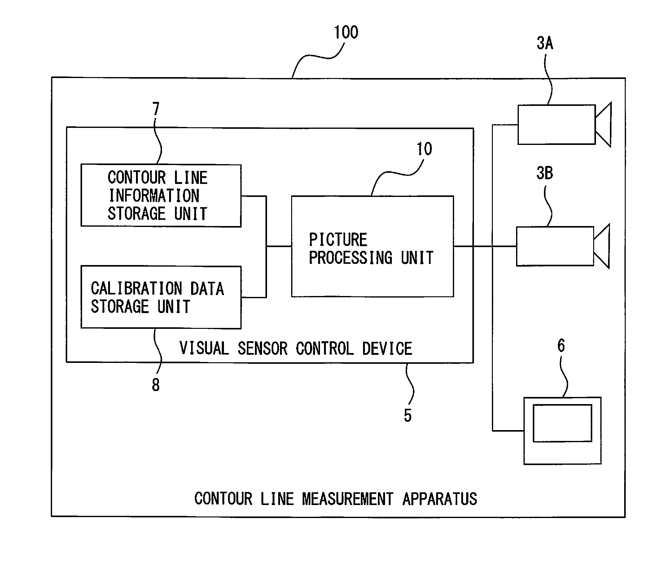
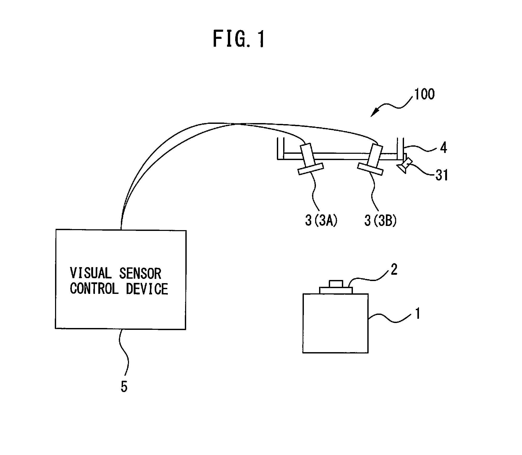
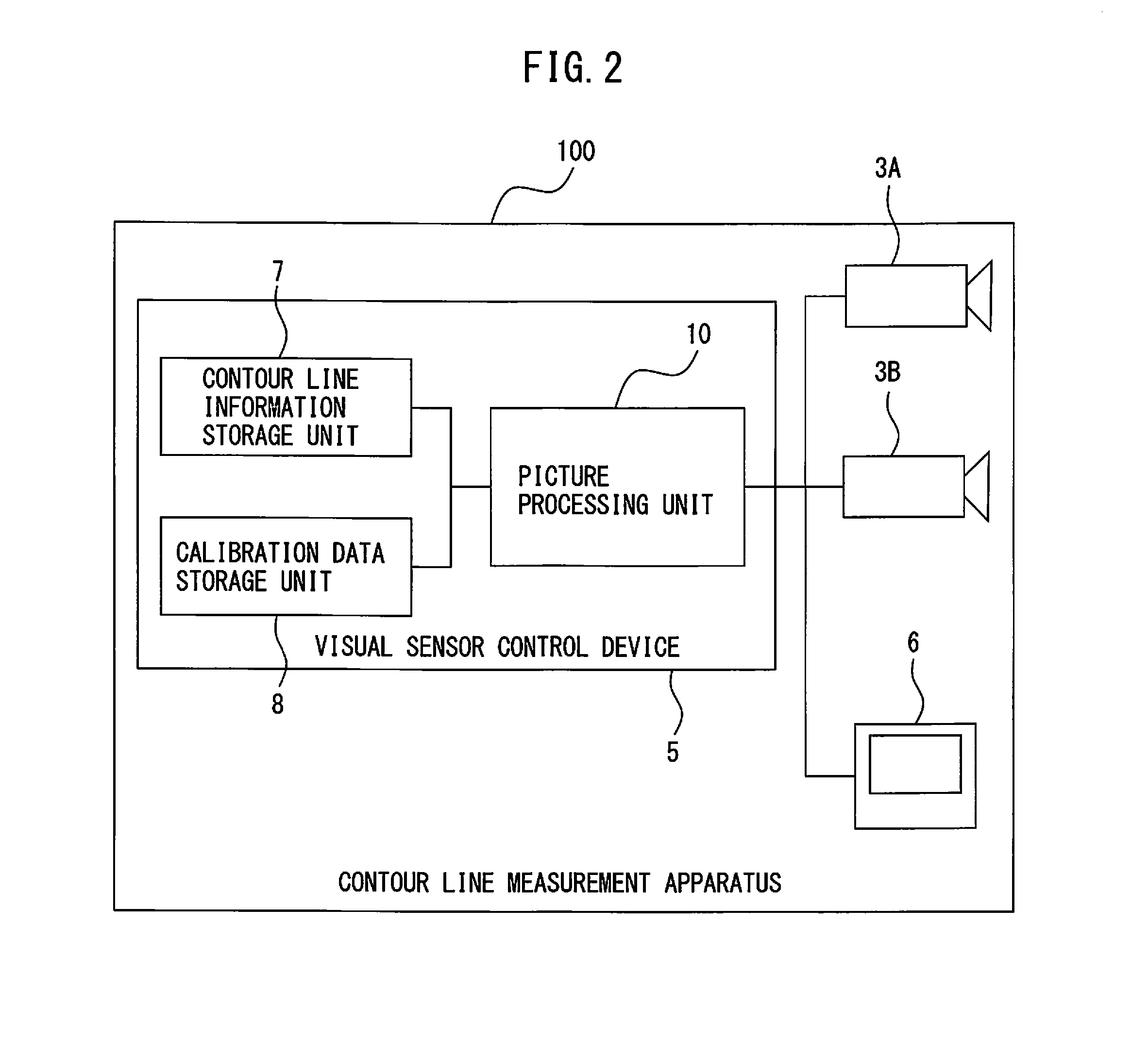
[0029]Hereinafter, a first embodiment of the present invention will be described with reference to FIGS. 1 to 13. FIG. 1 is a diagram illustrating a principal configuration of a contour line measurement apparatus 100 according to the first embodiment of the present invention. The contour line measurement apparatus 100 includes a pair of cameras 3 (first camera 3A and second camera 3B) for imaging a workpiece 2 as an object placed on a work bench 1, and a visual sensor control device 5 which communicates with the first camera 3A and the second camera 3B to calculate a contour line shape of the workpiece 2. Note that a shape of the workpiece 2 is defined by a contour line (contour line 2a in FIG. 5). Accordingly, a contour line shape is calculated so as to specify a workpiece shape.

[0030]The cameras 3 are electronic cameras having an imaging element, such as a charge coupled device (CCD), and a well-known light receiving device having a function in which an imaging surface (on a CCD a...

second embodiment

[0069]Hereinafter, a second embodiment of the present invention will be described with reference to FIGS. 14 to 18. Note that, hereinafter, the parts identical to those in FIGS. 1 to 10 are indicated by the identical reference signs, and the difference from the first embodiment will be mainly described. The second embodiment relates to a robot system including the contour line measurement apparatus 100, in which at least one of the pair of cameras 3A, 3B or the workpiece 2 are provided in a movable manner by using a robot.

[0070]FIG. 14 is a diagram illustrating a principal configuration of a robot system 200 according to the second embodiment of the present invention. As illustrated in FIG. 14, the robot system 200 includes the pair of cameras 3A, 3B, the visual sensor control device 5 which communicates with the pair of cameras 3A, 3B to calculate the contour line shape of the workpiece 2, a robot 60 which supports the pair of cameras 3A, 3B, and a robot control device 65 for contr...

modified examples

[0095]Such modifications of the above first embodiment and the second embodiment as described below are possible. A position posture measurement unit (for example, a three dimensional measurement sensor 31 in FIG. 1) for measuring a position and posture of the workpiece 2 may be additionally provided, and the position and posture of the workpiece 2 which has been measured in the position posture measurement unit may be stored in the contour line information storage unit 7. In this case, for example, the reference contour line image calculation unit 14 may alter, on the basis of the measured position and posture of the workpiece 2, workpiece position information stored in the contour line information storage unit 7, and project the reference contour line based on the altered workpiece position information on the pictures. Thereby, even when the workpiece 2 is disposed at a position different from a workpiece position stored in the contour line information storage unit 7, the contour ...


PUM


Abstract

A contour line measurement apparatus includes an edge line extraction unit for setting a picture processing region and extracting an edge line from an object picture in each of the regions, an edge point generation unit for generating edge points which are intersections of the edge lines and epipolar lines, a corresponding point selection unit for selecting, from the plurality of edge points, a pair of edge points corresponding to the same portion of the reference contour line, and a three dimensional point calculation unit for calculating a three dimensional point on the contour line of the object on the basis of lines of sight of cameras which pass the pair of edge points.

Description

BACKGROUND OF THE INVENTION[0001]1. Field of the Invention[0002]The present invention relates to a contour line measurement apparatus for measuring a three dimensional contour line shape of an object by using a stereo camera, and a robot system.[0003]2. Description of the Related Art[0004]To perform various operations on a workpiece by using an industrial robot, recognizing a three dimensional contour line shape of the workpiece is required. When the workpiece has no individual difference, information on a contour line shape of the workpiece can be obtained on the basis of design data. However, for example, when the workpiece is a cast, the workpiece has an individual difference for each casting mold, and consequently measuring a contour line shape of each workpiece is required.[0005]Regarding this point, conventionally, an apparatus in which accurate three dimensional contour line information is obtained by a stereo method using two cameras (for example, Japanese Laid-open Patent A...

Claims


Application Information

Patent Timeline
Patent Type & Authority Applications(United States)
IPC IPC(8): G06T7/00B25J9/16G01B11/24G06T7/60G06V10/44G06V10/60H04N5/225H04N5/247
CPCG06K9/4661G06T7/60G06K9/52H04N5/2251B25J9/1697G06T7/0044G06T7/0085G01B11/24G06K9/4604H04N5/247Y10S901/09G06T7/001G06T2207/10012G06T2207/10028G06T2207/30164G05B2219/37359G05B2219/40564G06T7/593G06V10/44G06V10/60H04N23/50H04N23/90
Inventor NAMIKI, YUUTAWARASHINA, FUMIKAZU
Owner FANUC LTD
Why Eureka
Try Eureka