Sensor, motion measurement system, and method of motion measurement

a technology of motion measurement and sensor, applied in the field of sensors, can solve the problems of deteriorating convenience, not only with swing motion in golf but also with any motion, and achieve the effect of reducing the time required

Inactive Publication Date: 2016-03-31
SEIKO EPSON CORP
View PDF0 Cites 16 Cited by
  • Summary
  • Abstract
  • Description
  • Claims
  • Application Information

AI Technical Summary

Benefits of technology

[0006]An advantage of some aspects of the invention is to provide a sensor that can be used for reducing the time required for detecting a stationary period of a measurement targe

Problems solved by technology

Consequently, it takes longer for the computing device to detect the stationary period of the user in the calibration, and the user has to remain stationary until the computing device detects the stationary period.
This raises the problem of deteriorating convenie

Method used


Image

  • Sensor, motion measurement system, and method of motion measurement
  • Sensor, motion measurement system, and method of motion measurement
  • Sensor, motion measurement system, and method of motion measurement

Examples


first embodiment

1-1. First Embodiment

1-1-1. Outline of Motion Measurement System

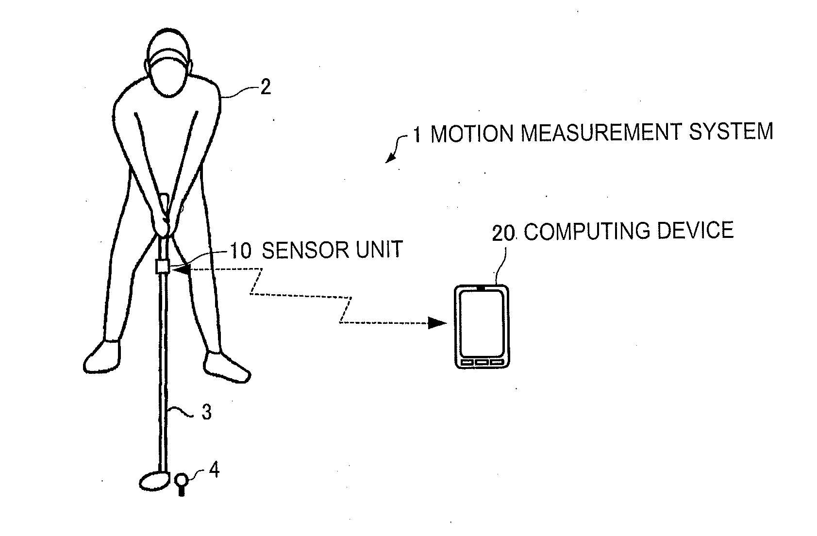
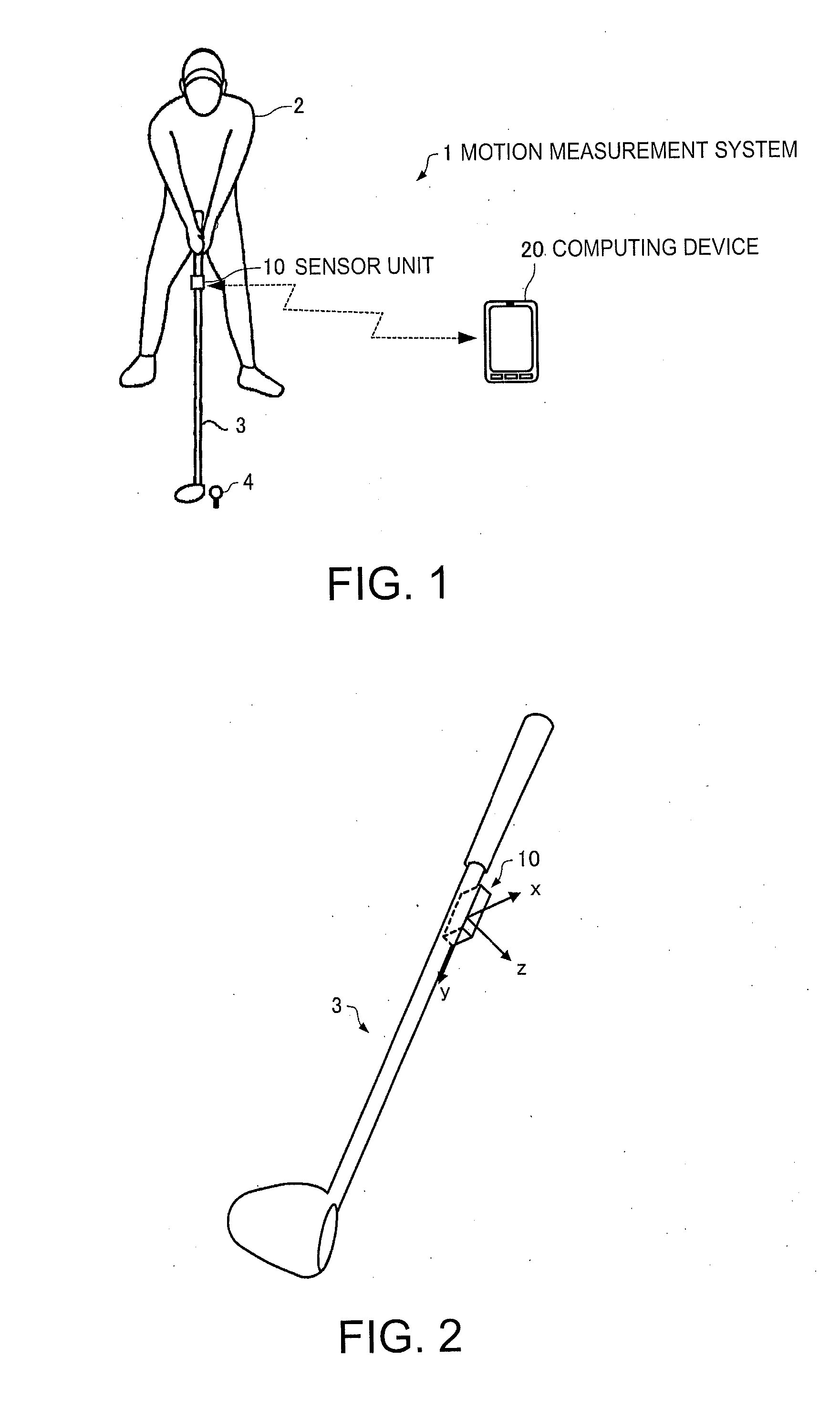
[0063]FIG. 1 is a view for explaining an outline of the motion measurement system in this embodiment. The motion measurement system. 1 in this embodiment includes a sensor unit (an example of a sensor) and a computing device 20.

[0064]The sensor unit 10 is capable of measuring an acceleration generated in each of the directions of three axes and an angular velocity generated around each of the three axes, and is installed on a golf club 3.

[0065]In the embodiment, as shown in FIG. 2, the sensor unit 10 is attached to a part of the shaft of the golf club 3, with one of three detection axes (x-axis, y-axis, z-axis), for example, the y-axis, aligned with the direction of the longitudinal axis of the shaft. Preferably, the sensor unit 10 is attached at a position close to the grip, to which the impact of ball hitting is hard to propagate and to which the centrifugal force at the time of a swing is not applied. The shaft is a ...

second embodiment

1-2. Second Embodiment

1-2-1. Outline of Motion Measurement System

[0168]A motion measurement system 1 according to a second embodiment includes a sensor unit 10 and a computing device 20, as in the first embodiment. In the second embodiment, the sensor unit 10 performs measurement at a first sampling rate (for example, 250 Hz) when set in the real-time mode, and performs measurement at a second sampling rate (for example, 1 kHz) when set in the buffering mode.

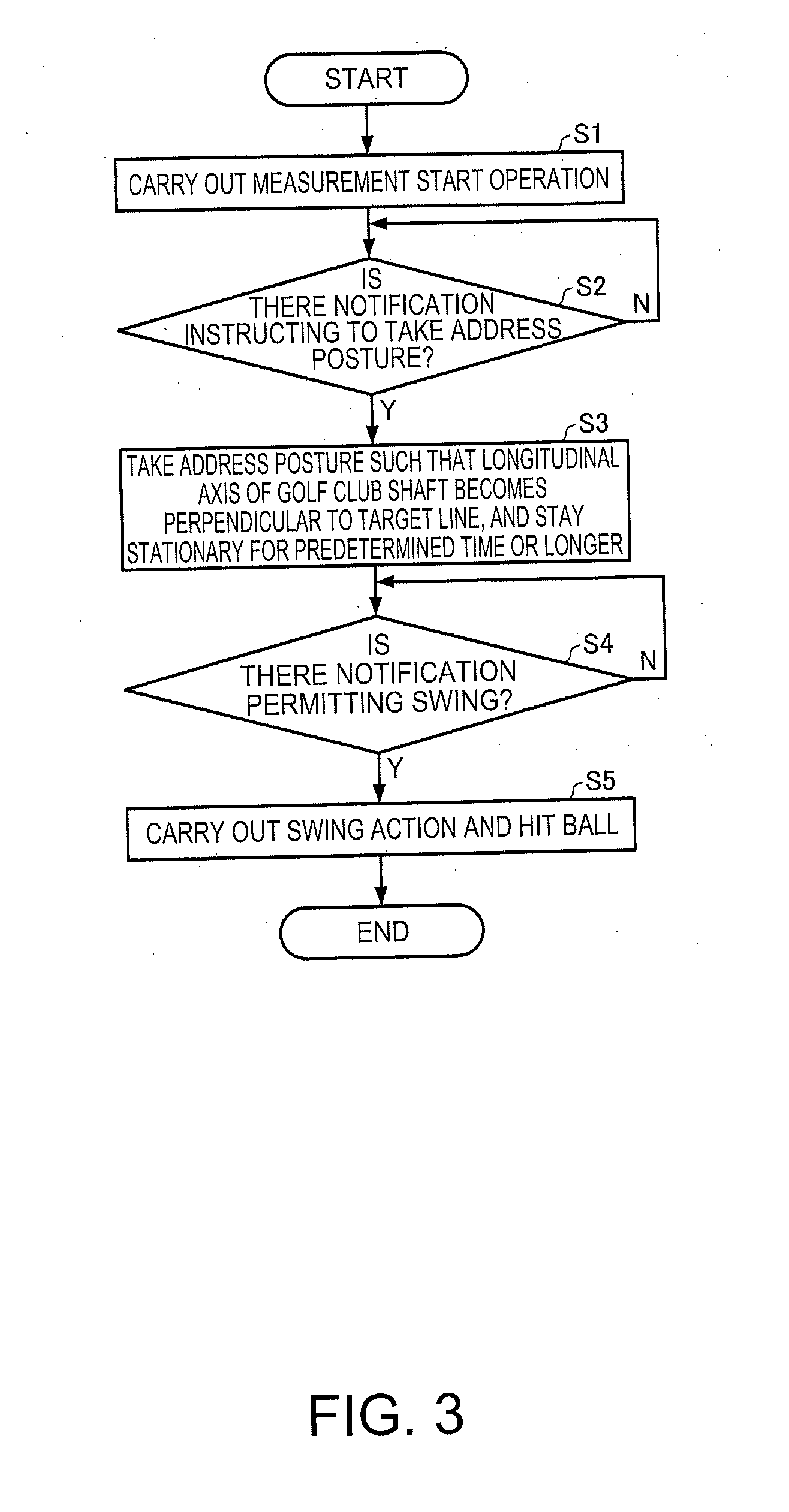
[0169]Specifically, in the second embodiment, in response to the measurement start operation by the user 2 in S1 of FIG. 3, the sensor unit 10 starts measurement at a first sampling rate. Then, during the stationary period when the user is stationary in S3 of FIG. 3 (an example of the stationary period of the measurement target), the sensor unit 10 carries out measurement at the first sampling rate and transmits measured data (an example of the first measured data) in the real-time mode to the computing device 20 (an example of ...

third embodiment

1-3. Third Embodiment

1-3-1. Outline of Motion Measurement System

[0219]A motion measurement system 1 according to a third embodiment includes a sensor unit 10 and a computing device 20, as in the first embodiment. In the third embodiment, the sensor unit 10 performs measurement at a predetermined sampling rate (for example, 1 kHz). When the output mode is the real-time mode, the sensor unit 10 detects a high-speed action by the user 2 on the basis of the measured data and switches the output mode to the buffering mode. Meanwhile, when the output mode is the buffering mode, the sensor unit 10 detects a low-speed action by the user 2 on the basis of the measured data and switches the output mode to the real-time mode.

[0220]Specifically, in the third embodiment, in response to the measurement start operation by the user 2 in S1 of FIG. 3, the sensor unit 10 starts measurement at a predetermined sampling rate. Then, during the stationary period when the user is stationary in S3 of FIG. 3...


PUM


Abstract

A sensor unit includes: a measuring unit; a first buffer which saves measured data measured by the measuring unit when outputting the measured data outside; a second buffer; and an output mode switching unit which switches an output mode for outputting the measured data outside. The output mode includes a real-time mode (first mode) in which the first buffer is overwritten with the measured data if there is no free space in the first buffer, and a buffering mode (second mode) in which the measured data is written in the second buffer if there is no free space in the first buffer and in which the measured data written in the second buffer is transferred to the first buffer if a free space is generated in the first buffer.

Description

BACKGROUND[0001]1. Technical Field[0002]The present invention relates to a sensor, a motion measurement system, and a method of motion measurement.[0003]2. Related Art[0004]JP-A-2008-73210 discloses a technique in which swing motion is measured on the basis of outputs from a three-axis acceleration sensor and a three-axis gyro sensor, which are inertial sensors, installed on a golf club. According to the technique of JP-A-2008-73210, the amount of calculation can be significantly reduced, compared with the case where image processing of a video of a swing filmed with a camera is carried out to analyze the swing. Also, according to the technique of JP-A-2008-73210, since a large device such as a camera is not necessary, there are few constraints on the place where the user performs a swing.[0005]In measuring a swing motion using an output from a sensor, there are cases where the user is made to become stationary for a few seconds before starting a swing and where a computing device c...

Claims


Application Information

Patent Timeline
IPC IPC(8): A63B24/00G01P1/00
CPCG01P1/00A63B24/0003G01P1/127G01P15/00G01D9/005
Inventor MITSUNAGA, SHINICHISHIBUYA, KAZUHIRO
Owner SEIKO EPSON CORP
Why Eureka
Try Eureka