Opening implement for accessory clasp

Inactive Publication Date: 2016-03-31
JAPAN LANDCARE TECH CO LTD
View PDF6 Cites 2 Cited by
  • Summary
  • Abstract
  • Description
  • Claims
  • Application Information

AI Technical Summary

Benefits of technology

[0004]The clasps of accessories are very small. Thus, it is very difficult to pick up the clasp between fingers, and relatively large force is required for the fingers to open the clasp. This means that opening such a clasp is not easy and burdensome, for example, for long-nailed women, and especially for elderly people whose finger-tip strengths are low. An object of the present disclosure is to solve the problems as described above.
[0005]According to a first aspect of the present disclosure, there is provided an opening implement for a ring-shaped clasp of an accessory, the clasp including: a body having a cutout part which allows a part of a linear accessory, to be used by being put around a part of a human body, to pass; a closing member configured to close the cutout part; a movable part connected to the closing member to open and close the closing member; and a fix

Problems solved by technology

Thus, it is very difficult to pick up the clasp between fingers, and relatively large force is required for the fingers to open the clasp.
This means that

Method used


Image

  • Opening implement for accessory clasp
  • Opening implement for accessory clasp
  • Opening implement for accessory clasp

Examples


first embodiment

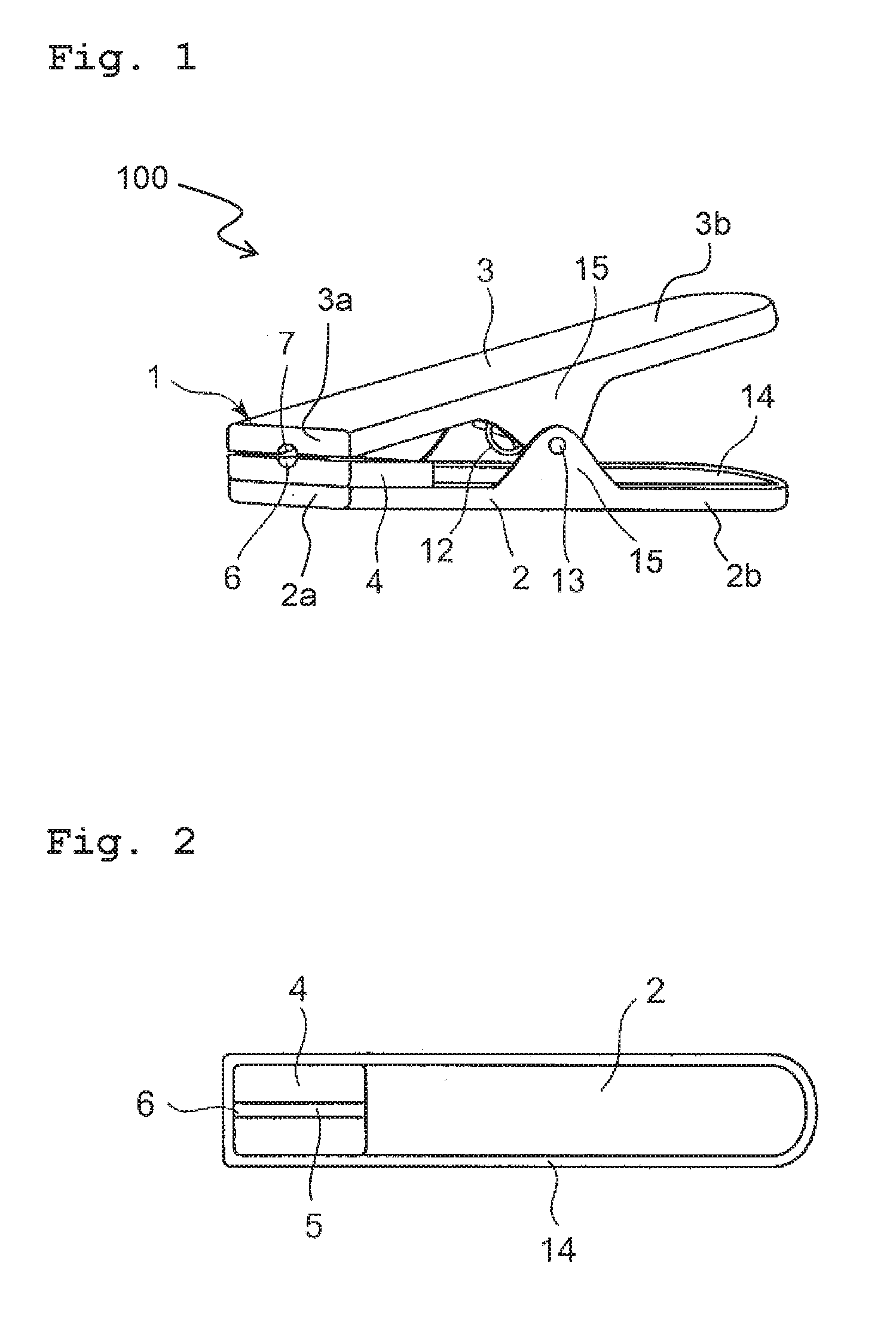
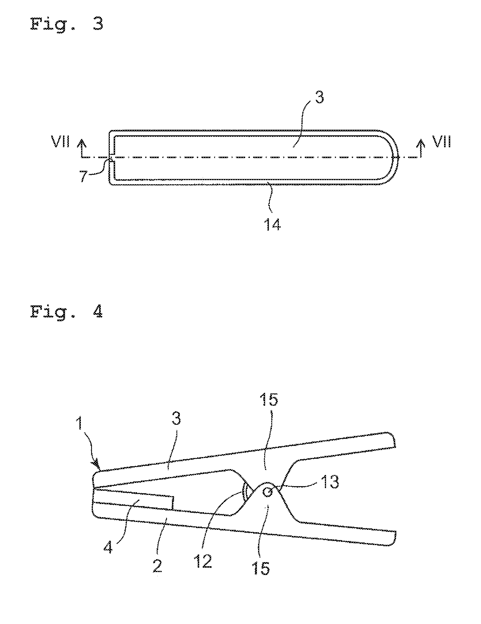
[0020]At first, how to use the first embodiment of the present disclosure will be explained below. An opening implement body 1 of an opening implement 100 according to the first embodiment is configured in such a manner that a lower movable wing 2 disposed on a lower side and an upper movable wing 3 disposed on an upper side are pivotably or movably attached to a rotary shaft 13 via their connection parts 15. The connection part 15 protruding from the lower movable wing 2 faces the connection part 15 protruding from the upper movable wing 3. An elastic body 4 is attached to a part of an end of the lower movable wing 2. In the elastic body 4, it is formed a recessed groove 5 extending in the longitudinal direction of the elastic body 4 and a lower recessed hole 6 at the end (FIG. 2). On a peripheral edge 14 provided at an end of the upper movable wing 3, it is formed an upper recessed hole 7 at a position corresponding to the lower recessed hole 6 (FIG. 3). The opening implement 100 ...

second embodiment

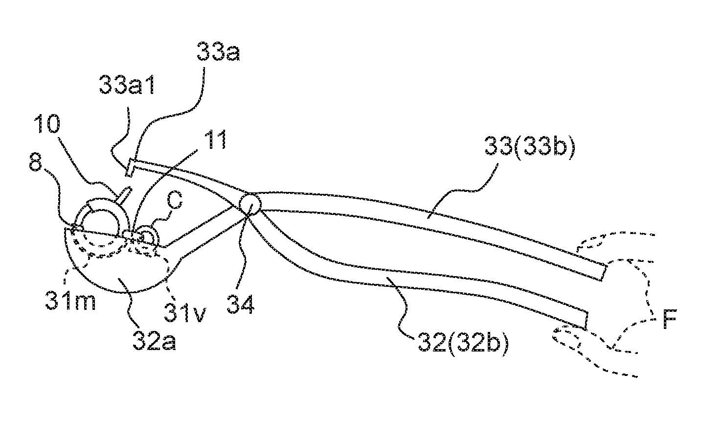
[0044]Subsequently, an explanation will be made about the second embodiment of the present disclosure with reference to FIGS. 11 to 13. An opening implement 300 according to the second embodiment is different from the opening implement 100 according to the first embodiment mainly in that a holding end 32a of a lower movable wing 32 includes a holding hole 31 which holds the clasp 8.

[0045]As depicted in FIG. 11, the opening implement 300 according to the second embodiment includes a lower movable wing 32 extending in a longitudinal direction (left-right direction of FIG. 11) and an upper movable wing 33 extending in the longitudinal direction. The lower movable wing 32 is connected integrally with the upper movable wing 33 via a rotary shaft 34. The lower movable wing 32 and the upper movable wing 33 can pivot about the rotary shaft 34.

[0046]One end of the lower movable wing 32 is the holding end 32a, and the other end, of the lower movable wing 32, including the vicinity thereof is ...

third embodiment

[0058]Subsequently, an explanation will be made about the third embodiment of the present disclosure with reference to FIG. 14. An opening implement 500 according to the third embodiment is different from the opening implements 100, 300 according to the first and second embodiments in that the opening implement 500 includes a holding bar 58 connected to a lower movable wing 52.

[0059]As depicted in FIG. 14, the opening implement 500 according to the third embodiment includes the lower movable wing 52 extending in a longitudinal direction (left-right direction of FIG. 14) and an upper movable wing 53 extending in the longitudinal direction. The lower movable wing 52 is connected integrally with the upper movable wing 53 via a rotary shaft 54. The lower movable wing 52 and the upper movable wing 53 can pivot about the rotary shaft 54.

[0060]One end of the lower movable wing 52 is a holding end 52a, and the other end including the vicinity thereof is a handle 52b. FIG. 14 depicts the hol...


PUM


Abstract

There is provided an opening implement for a ring-shaped clasp of an accessory, the clasp including: a body having a cutout part, a closing member to close the cutout part, a movable part connected to the closing member to open and close the closing member, and a fixed part. The opening implement includes a first holding part to hold the fixed part, a second holding part configured to hold the movable part; and a connection part connecting the first holding part and the second holding part. The first holding part includes a housing part configured to house any of a part of the spring clasp and a part of the lobster clasp. Any of the spring clasp and the lobster clasp is held by only the first holding part via the housing part.

Description

[0001]This application is a Continuation Application of International Application No. PCT / JP2014 / 064759 claiming the conventional priority of Japanese Utility-Model Application No. 2013-003494 filed on Jun. 3, 2013. The disclosures of Japanese Utility-Model Application No. 2013-003494 and International Application No. PCT / JP2014 / 064759 are incorporated herein by reference in their entirety.TECHNICAL FIELD[0002]The present disclosure relates to an opening implement for a catch (clasp) of an accessory that opens the clasp of the accessory easily.BACKGROUND ART[0003]As the opening implements for catches or clasps, such as spring clasps and lobster clasps, of accessories, those being made of metal or wood to have small tweezer-like shapes have been conventionally used.SUMMARY[0004]The clasps of accessories are very small. Thus, it is very difficult to pick up the clasp between fingers, and relatively large force is required for the fingers to open the clasp. This means that opening such...

Claims


Application Information

Patent Timeline
IPC IPC(8): B25B7/02A44B13/02
CPCA44B13/02B25B7/02A44B99/00A44C15/003A47G25/901B25B5/06B25B7/08
Inventor KIMURA, MASAKO
Owner JAPAN LANDCARE TECH CO LTD
Why Eureka
Try Eureka