
Method In Forklift Truck For Determining A Load Position In A Load Rack

a forklift truck and load position technology, applied in the direction of process and machine control, image enhancement, instruments, etc., can solve the problems of damage to the load or the load rack, the forklift truck is not positioned correctly, and the inability to describe how to avoid bad position control

Active Publication Date: 2016-03-31
TOYOTA MATERIAL HANDLING MFG SWEDEN
View PDF3 Cites 27 Cited by
  • Summary
  • Abstract
  • Description
  • Claims
  • Application Information

AI Technical Summary

Benefits of technology

The present disclosure provides a solution for determining the position of a load in a load rack on a forklift truck. This is achieved by using optical detection means and landmarks on the load rack. The forklift truck automatically or manually positions itself in front of the load rack where the load should be left. The optical detection means capture images of the landmarks on the load rack and process them to determine the position of the load carrier relative to the load rack. This reference position is then used to compare with the position of a second landmark on the load rack to determine the position of the load on the second height. The method compensates for any mismatches or deviations in the load rack and forklift truck by determining a reference position and comparing it with the second position. The forklift truck is then able to accurately position itself and deposit the load.

Problems solved by technology

However the prior art does not describe how to avoid bad position control.
If the camera has low positioning performance there is a risk that the forklift truck is not positioned correctly when e.g. a load should be lifted.
This may result in damage of the load or load rack when handling the load.
Yet another problem with prior art systems that uses landmarks is that they require that the camera at the forklift truck is exactly positioned at the forklift truck, so that the camera can be used for exact positioning of the cargo and the forks.
If the camera is not positioned correctly on the forklift truck there is a risk that the forklift truck is not positioned correctly when e.g. a load should be deposited or picked-up.
This may result in damage of the load or load rack when handling the load.
Since the cameras on the prior art systems are sensitive to exact positioning, the prior art systems are also sensitive to shocks, since a shock may cause that the camera moves from its position.

Method used


Image

  • Method In Forklift Truck For Determining A Load Position In A Load Rack
  • Method In Forklift Truck For Determining A Load Position In A Load Rack
  • Method In Forklift Truck For Determining A Load Position In A Load Rack

Examples


Embodiment Construction

[0022]The general object or idea of embodiments of the present disclosure is to address at least one or some of the disadvantages with the prior art solutions described above as well as below. The various steps described below in connection with the figures should be primarily understood in a logical sense.

[0023]The terminology used herein is for the purpose of describing particular aspects of the disclosure only, and is not intended to limit the disclosure to any particular embodiment. As used herein, the singular forms “a”, “an” and “the” are intended to include the plural forms as well, unless the context clearly indicates otherwise.

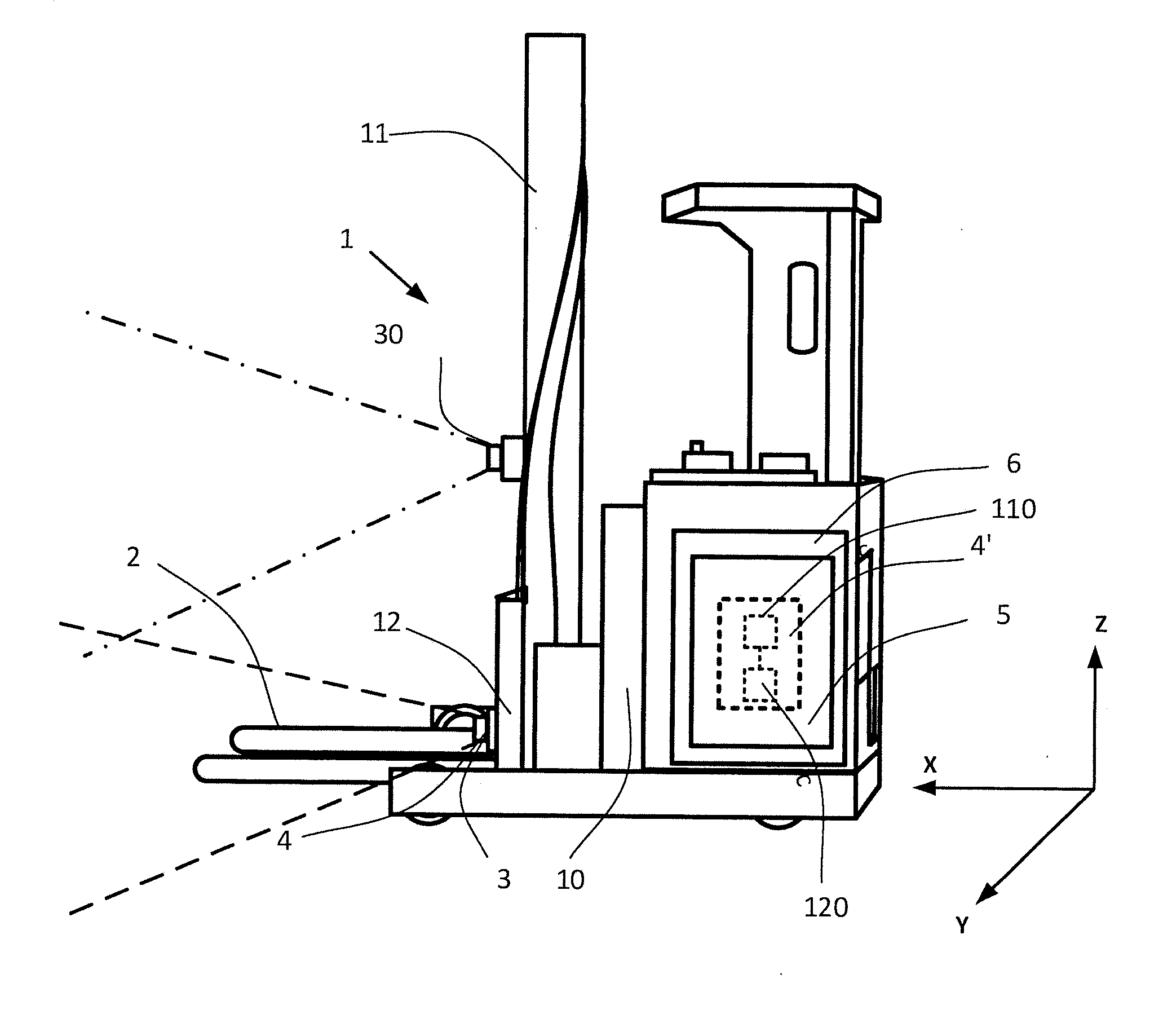
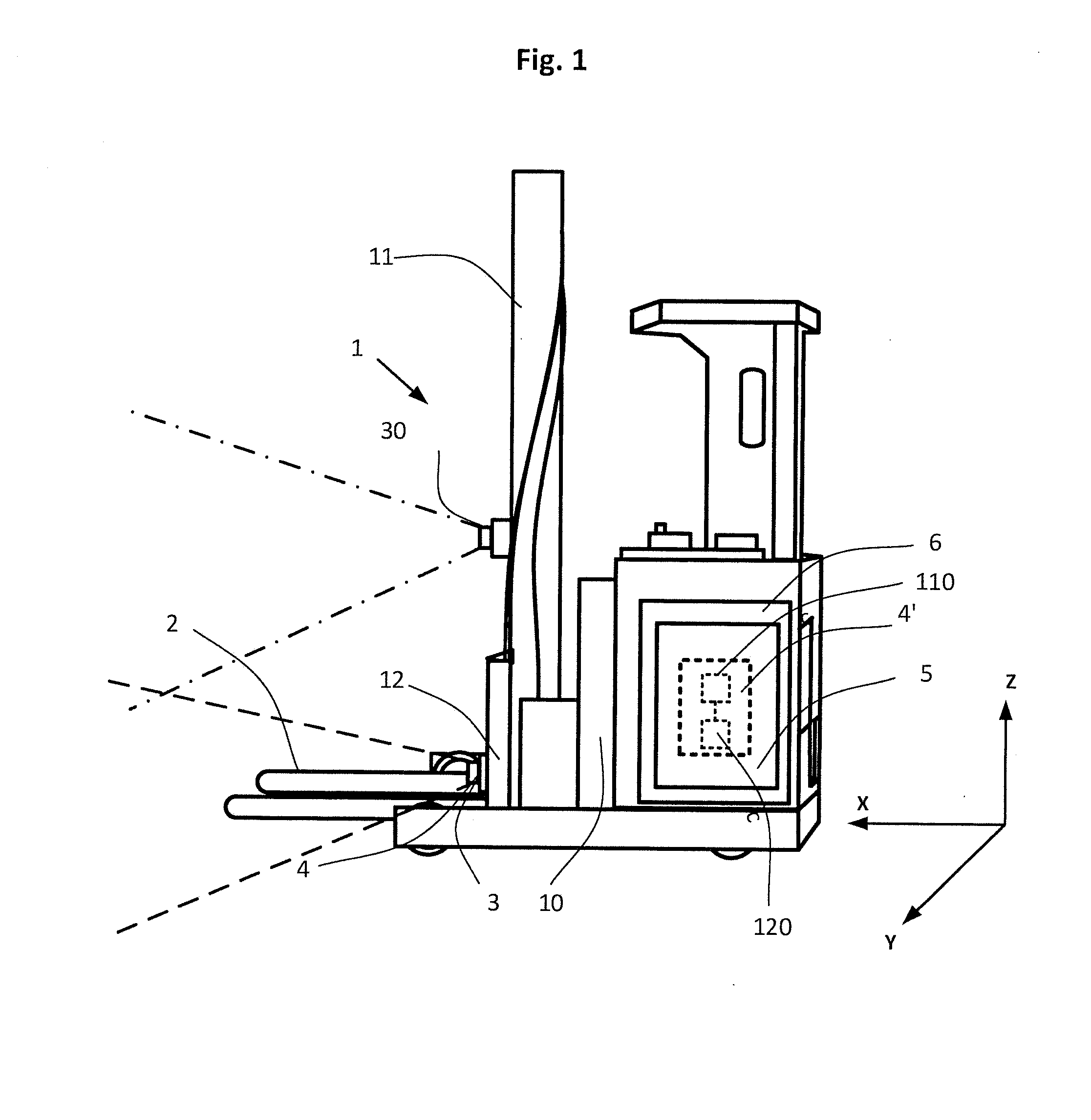
[0024]The present disclosure relates to the area of forklift trucks 1, such as disclosed in FIG. 1. In particular it relates to forklift trucks 1 that are electrical and used within a warehouse. Even more particularly, it relates to forklift trucks that are arranged such that they can navigate and move autonomously within a warehouse, for material han...


PUM


Abstract

The present disclosure relates to a method performed in a forklift truck, for determining a load position in a load rack. The forklift truck includes optical detection means movable with a load carrier. The method includes the steps of determining a reference position related to the optical detection means of a first land mark located on a first height of the load rack based on the position of the first landmark in a first image captured by the optical detection means; determining a second position related to the optical detection means of a second land mark located on a second height of the load rack based on the position of the second landmark in a second image captured by the optical detection means at a predetermined height; and determining a load position on the second height based on a comparison between the reference position and the second position.

Description

CROSS-REFERENCE TO RELATED APPLICATIONS[0001]The present application claims the benefit of European Patent Application No. 14186474.4 filed Sep. 25, 2014, which is fully incorporated herein by reference.STATEMENT REGARDING FEDERALLY SPONSORED RESEARCH OR DEVELOPMENT[0002]Not applicable.FIELD OF THE INVENTION[0003]The present disclosure relates to a method performed in forklift truck, for determining a load position in a load rack. The disclosure also relates to a forklift truck for determining a load position in a load rack.BACKGROUND OF THE INVENTION[0004]From US 2004 / 0073359 it is known to use a camera for picking up an image of a landmark 17 and acquire an image data of the landmark 17 affixed to the load rack. The described system of this document uses the land marks for position control of the forklift truck. However the prior art does not describe how to avoid bad position control. For example in the prior art systems the camera at the fork lift truck has to have high position...

Claims


Application Information

Patent Timeline
Patent Type & Authority Applications(United States)
IPC IPC(8): B66F9/075G06T7/00H04N13/02
CPCB66F9/0755H04N13/0203G06T2207/30252G06T2200/04G06T2207/10012G06T7/0042G05D1/0246B66F9/24G06T7/73H04N13/204
Inventor SVENSSON, RUNEPERSSON, MAGNUSFRID, HAKAN
Owner TOYOTA MATERIAL HANDLING MFG SWEDEN
Features
  • Generate Ideas
  • Intellectual Property
  • Life Sciences
  • Materials
  • Tech Scout
  • Unparalleled Data Quality
  • Higher Quality Content
  • 60% Fewer Hallucinations
Learn More