Acoustic building infiltration measurement system

a measurement system and infiltration technology, applied in the field of leakage or infiltration detection, can solve the problems of increasing the difficulty and cost of sealing the building, affecting the operation of the measurement system, and the method is not practical for large buildings

Active Publication Date: 2016-03-31
ILLINOIS INSTITUTE OF TECHNOLOGY +1
View PDF3 Cites 11 Cited by
  • Summary
  • Abstract
  • Description
  • Claims
  • Application Information

AI Technical Summary

Benefits of technology

This patent describes a method, system, and computer program for detecting leaks in a structure using sound waves. The system measures the pressure and velocity of the sound waves both inside and outside of the structure, and uses this data to determine if there is a leak. The system can also include a microphone array to collect the sound waves and a computer program to analyze the data. Overall, this technology provides a more accurate and reliable way to detect leaks in structures.

Problems solved by technology

Measuring the infiltration in commercial buildings is difficult because of the physical size and measurements cannot be made during construction which means sealing the building becomes more difficult and expensive.
This method works well for small buildings but is impractical for large buildings.
Further, the entire building envelope must be constructed before the method can be used.
The tracer technique can take a very long time (especially on buildings with low infiltration), is more difficult to apply in large buildings, and also needs a completed building enclosure to utilize.
Others have attempted to correlate sound transmission loss to infiltration rates with limited success.
While correlations do exist, they are specific to the exact details of wall construction and infiltration location so one cannot develop correlations on one building and use them on another and hence the method cannot be used as a general method for measuring infiltration.
Further, there is no general method on how to estimate the correlations without actual measurement of the building (i.e. from drawings and computer models).
Leakages in a gas-storing containers and air-conditioned buildings are serious safety and economic problem to the society.
However, the present leakage detection methods such as smoke stick method are not very effective and involves a lot of human resource.

Method used


Image

  • Acoustic building infiltration measurement system
  • Acoustic building infiltration measurement system
  • Acoustic building infiltration measurement system

Examples


examples

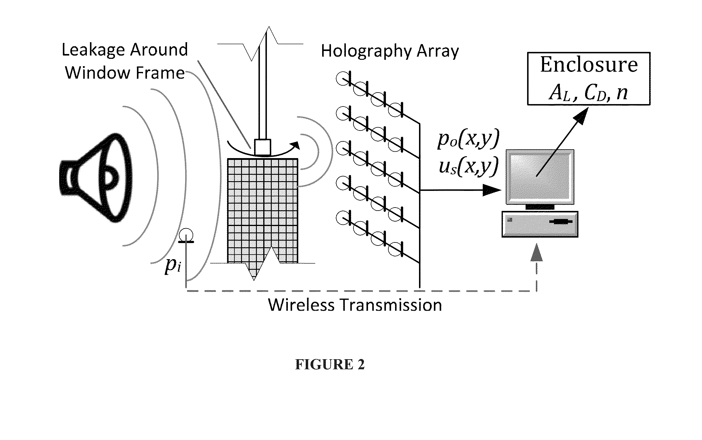
[0127]This section describes experiments regarding certain implementations of the present invention. To qualify various algorithms of NAH a loudspeaker experiment was designed. A sub-woofer of diameter 10 inches was placed in an anechoic chamber located at IIT Fluid Dynamics Research Center. Simultaneous measurement at all the points in the hologram is not necessary for the frequency domain NAH analysis that are used in this study. Therefore, a single microphone fixed on a motorized traverse (shown in FIG. 2(a)) is used to record the sound signal on a two dimensional surface (which is called hologram surface). The hologram surface is located at distance 0.5 inches from the source. A quarter inch, B & K (model 4338) microphone is used here with appropriate power supply and filter. 204800 samples are acquired using an NI DAQ module at a rate of 100 kHz. The measurement aperture is 28 in×28 in rectangle with 113×113 measurement points (0.25 in between adjacent measurement points). A si...


PUM


Abstract

Systems and methods of detecting and identifying a leak from a container or building. Acoustic pressure and velocity are measured. Acoustic properties are acquired from the measured values. The acoustic properties are converted to infiltration / leakage information. Nearfield Acoustic Holography (NAH) may be one method to detect the leakages from a container by locating the noise sources.

Description

STATEMENT OF GOVERNMENT INTEREST[0001]The United States Government has rights in the invention described herein pursuant to Contract No. DE-AC02-06CH11357 between the United States Department of Energy and UChicago Argonne, LLC, as operator of Argonne National Laboratory.FIELD OF THE INVENTION[0002]The present invention generally relates to leakage or infiltration detection. More specifically, the present invention relates to systems and methods of identifying and converting acoustic properties to infiltration or leakage information.BACKGROUND OF THE INVENTION[0003]Building air infiltration, the uncontrolled leakage of air in and out of buildings, accounts for over 30% of total heating load of commercial buildings in the US. Measuring the infiltration in commercial buildings is difficult because of the physical size and measurements cannot be made during construction which means sealing the building becomes more difficult and expensive.[0004]Two methods for measuring building infilt...

Claims


Application Information

Patent Timeline
IPC IPC(8): G01M3/24G01N29/04G01N29/44
CPCG01M3/24G01N29/04G01N2291/269G01N2291/011G01N29/44G01N29/024G01N29/0663G01N29/46
Inventor MUEHLEISEN, RALPH, T.RAMAN, GANESH
Owner ILLINOIS INSTITUTE OF TECHNOLOGY
Why Eureka
Try Eureka