Use of packet header extension for layer-3 direct server return

a technology of direct server return and packet header extension, which is applied in the field of load balancing in the computer network, can solve the problems of significant drawbacks in the type of network configuration, rise in the risk of the load balancer acting as a bottleneck, and consequently suffer the effects of network performan

Active Publication Date: 2016-03-31
A10 NETWORKS
View PDF21 Cites 15 Cited by
  • Summary
  • Abstract
  • Description
  • Claims
  • Application Information

AI Technical Summary

Benefits of technology

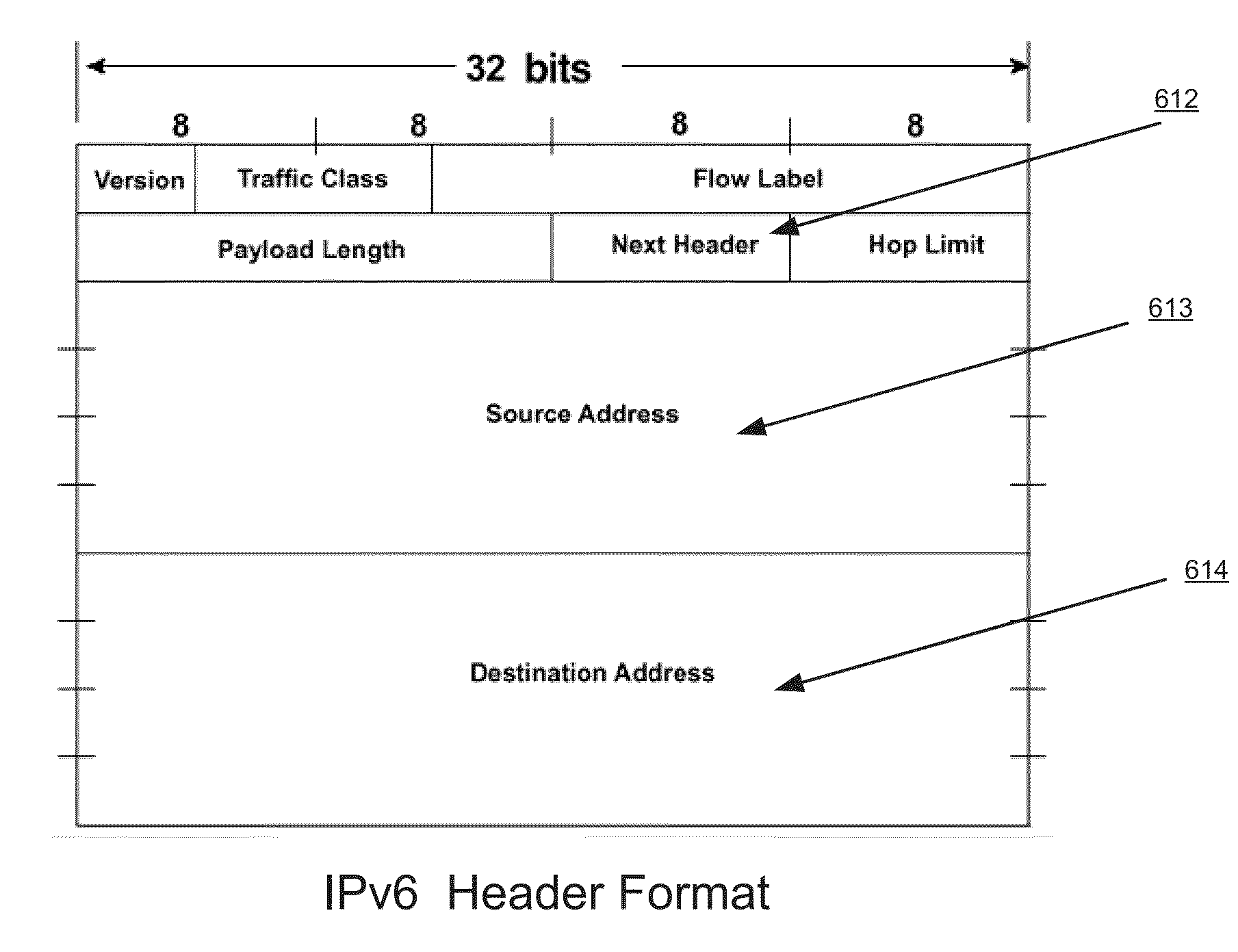
[0009]Accordingly, a need exists for a method and apparatus that transmit a VIP address requested by a client from a load balancer to a server behind the VIP in an efficient and flexible manner within a network using L3DSR load balancing. Additionally, a need exists for transmitting the VIP address from the load balancer to the server using an extension header in an IPv6 packet so that none of the bits within the main IPv6 header itself need to be consumed for this purpose.

Problems solved by technology

This type of network configuration, however, has a major drawback.
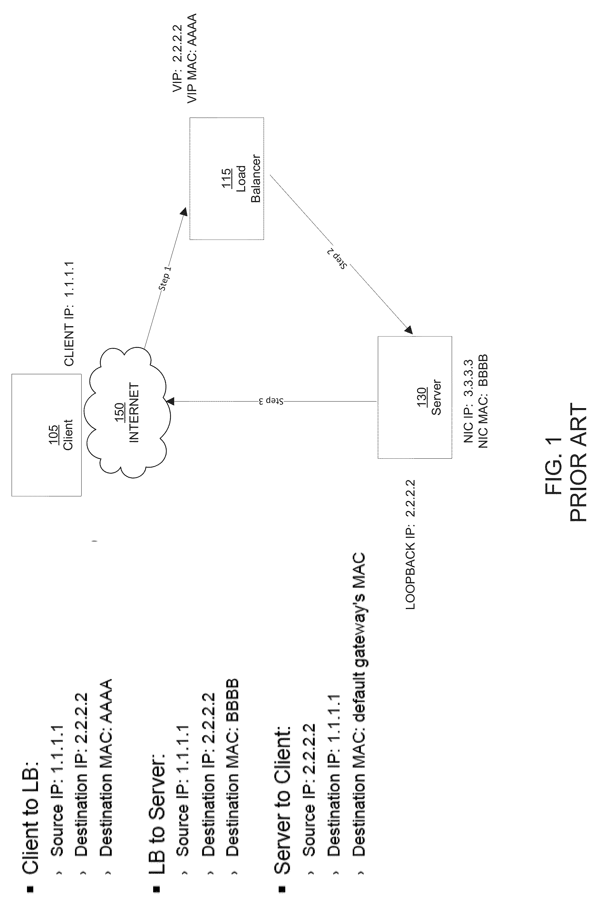
As traffic needs to transit or pass through the load balancer on high traffic networks, the risk of the load balancer acting as a bottleneck rises considerably and network performance consequently suffers.
One significant drawback of L2DSR is that because the load balancer 115 forwards incoming packets from the client 105 to the server by changing the destination MAC addresses of the incoming packets on the fly, both the load balancer 115 and the server 130 unfortunately need to be on the same L2 network segment.
The physical location of the servers is restricted and flexibility within the data center is greatly limited.
This creates instability on very large networks, e.g., networks with more than 10 k hosts.
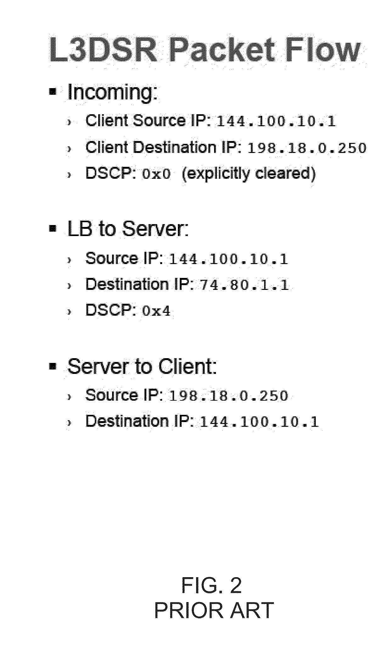
While L3DSR improves on L2DSR by not requiring the server and the load balancer to be on the same network segment, it is also restrictive because it relies on, and thereby consumes, the DSCP field of an IPv4 header to communicate the destination VIP address.
Second, use of the DSCP bits for L3DSR prevents them for being used for other purposes, e.g., to provide Quality of Service (QoS) information.

Method used


Image

  • Use of packet header extension for layer-3 direct server return
  • Use of packet header extension for layer-3 direct server return
  • Use of packet header extension for layer-3 direct server return

Examples


Embodiment Construction

[0029]Reference will now be made in detail to the various embodiments of the present disclosure, examples of which are illustrated in the accompanying drawings. While described in conjunction with these embodiments, it will be understood that they are not intended to limit the disclosure to these embodiments. On the contrary, the disclosure is intended to cover alternatives, modifications and equivalents, which may be included within the spirit and scope of the disclosure as defined by the appended claims. Furthermore, in the following detailed description of the present disclosure, numerous specific details are set forth in order to provide a thorough understanding of the present disclosure. However, it will be understood that the present disclosure may be practiced without these specific details. In other instances, well-known methods, procedures, components, and circuits have not been described in detail so as not to unnecessarily obscure aspects of the present disclosure.

Notatio...


PUM


Abstract

A method for performing Layer 3 direct server return is disclosed. The method comprises receiving an IP packet from a client device over a communication network. Further, the method comprises extracting a virtual IP address from a destination header field of the IP packet. Subsequently, the method comprises determining a server to which to forward the IP packet and inserting an IP address of the server in the destination header field of the IP packet. Next, the method comprises inserting the virtual IP address in an extension header for the IP packet. Finally, in one embodiment, the method comprises transmitting the IP packet to the server over the communication network.

Description

FIELD OF THE INVENTION[0001]Embodiments according to the present invention relate generally to load balancing in a computer network and more particularly to direct server return load balancing in a computer network.BACKGROUND OF THE INVENTION[0002]Load balancers are typically used in a computer communication network to distribute traffic load across clustered CPUs and network infrastructure in order to increase network reliability and performance while introducing the benefits of redundancy. In traditional networks employing load balancers, incoming packets having requests from clients were assigned a Virtual IP (“VIP”) on the load balancer itself and then the load balancer would pass the request to the appropriate server with negligible modification to the packets. The server would then respond to the load balancer with the required data, which would be relayed onto the client by the load balancer.[0003]This type of network configuration, however, has a major drawback. Incoming req...

Claims


Application Information

Patent Timeline
Patent Type & Authority Applications(United States)
IPC IPC(8): H04L29/08H04L29/12
CPCH04L61/2503H04L61/6068H04L67/1008H04L69/22H04L2101/659H04L67/1001
Inventor FRIEDEL, MICHAELKARAMPURWALA, HASNAIN
Owner A10 NETWORKS
Why Eureka
Try Eureka