

Methods and apparatus for expelling a projectile
- Summary
- Abstract
- Description
- Claims
- Application Information
AI Technical Summary
Benefits of technology
Problems solved by technology
Method used
Image

Examples
Embodiment Construction
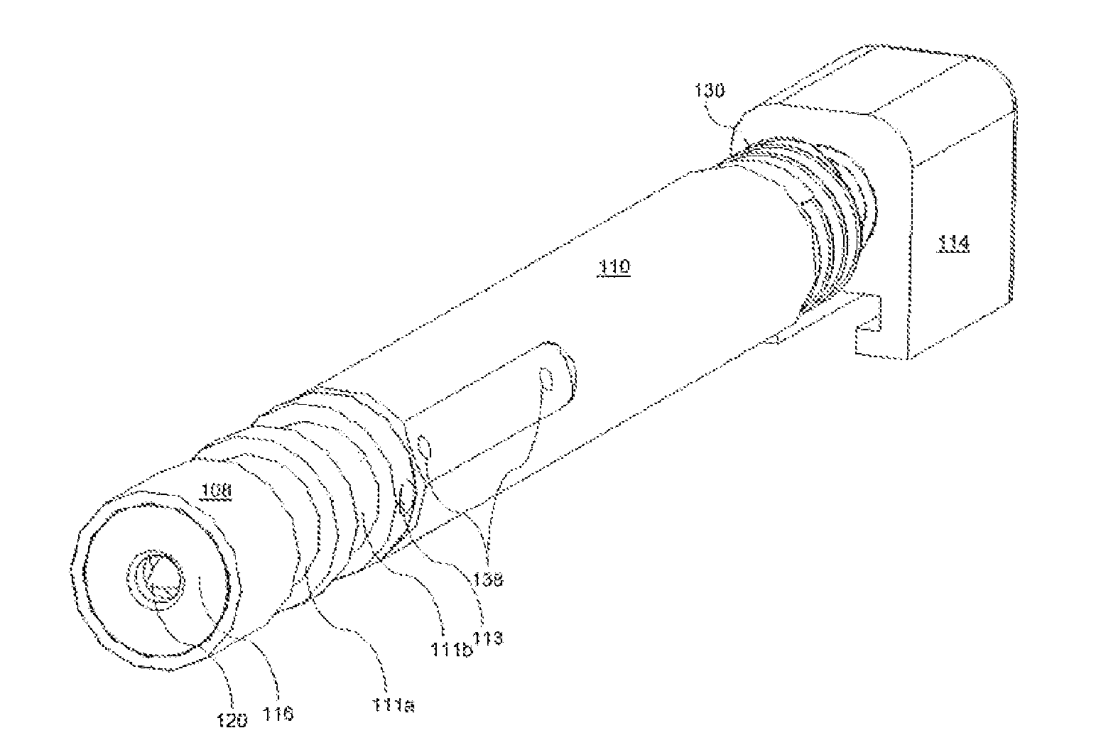
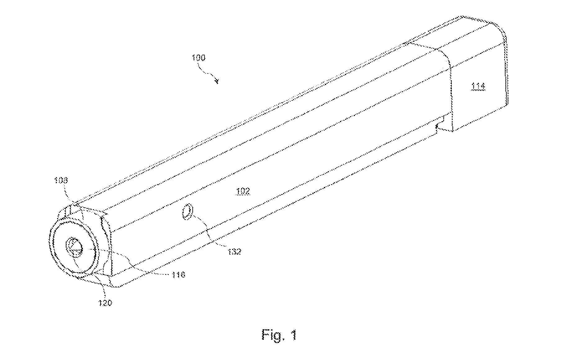
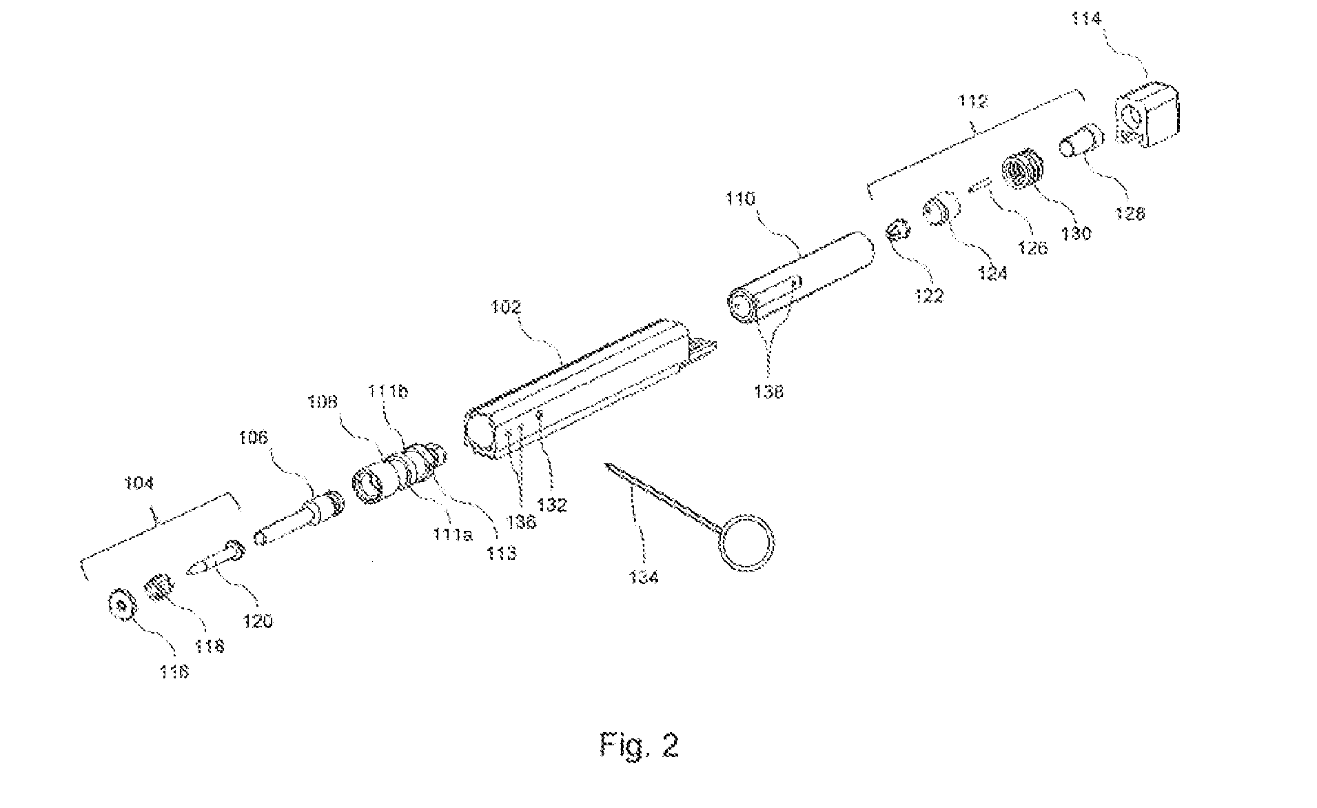
[0038]FIG. 1 shows an assembled ‘single shot’ nail gun tool according to one embodiment of the invention. The internal components are shown in an exploded view in FIG. 2, and various components, assembled or partly assembled, are shown in FIGS. 3 and 4, as explained in greater detail below.
[0039]With reference then to FIGS. 1-4, a nail gun tool 100 according to one embodiment of the invention has a generally elongate cylindrical body sized to be held inside the hand of a user which comprises an outer housing 102, which in this example comprises 5083 N8 Aluminium, but in other examples could comprise a composite material (in particular but not exclusively reinforced plastic or polymer composites), moulded plastic or even rolled cardboard. Inside the housing 102 are a nail assembly 104, a slide hammer 106, a cylinder 108, a barrel 110, a firing assembly 112, and an end block 114. In this example, the barrel 110 comprises steel (specifically EN24 Steel), but other materials which are c...
PUM
| Property | Measurement | Unit |
|---|---|---|
| Force | aaaaa | aaaaa |
| Pressure | aaaaa | aaaaa |
Abstract
Description
Claims
Application Information