Solar panel installation tool

a technology for installing tools and solar panels, which is applied in the direction of manufacturing tools, heat collector mounting/supports, light and heating apparatus, etc. it can solve problems such as crooked solar panels, and achieve the effects of reducing the likelihood of tool wear and replacement, easy sliding on and off a mounting rack, and little effor

Active Publication Date: 2016-04-07
KING KEVIN
View PDF7 Cites 5 Cited by
  • Summary
  • Abstract
  • Description
  • Claims
  • Application Information

AI Technical Summary

Benefits of technology

[0012]The disclosed solar panel installation tool allows for adjustable layout of panels (landscape or portrait) and easily slides on and off a mounting rack with little effort, even after a solar panel has been installed. The solar panel installation tool can engage the mounting rack and does not require the tool to be physically screwed down. While engaged with the rack, it allows for adjustment of either corner of the solar panel in either direction. The rail engaging foot of the solar panel installation tool can be replaced with an alternative foot to accommodate any type of manufactured racking system, so the device is not limited to one type of racking system. The solar panel installation tool allows the solar panel to sit flush on racking while the solar panel is being tightened down. It is specially designed with shock absorption which allows for the dispersion of weight from the solar panel without disturbing the temporary mounting of the tool to the racking. The solar panel installation tool has the measurements for solar panel placement built into the tool, in the form of preset distances built into the coarse adjustment. It is designed for individual panel mounting, which proves useful in mounting arrays with customized layouts. The solar panel installation tool does not require screws to tighten to the racking which reduces the likelihood of the tool wearing out and needing to be replaced.

Problems solved by technology

The problem is when an array of rectangular solar panels is placed edge to edge on a roof; if they are not perfectly parallel with part of the roof, such as the lower edge of the roof, it is very obvious that they are not parallel, and the solar panel looks crooked.

Method used


Image

  • Solar panel installation tool
  • Solar panel installation tool
  • Solar panel installation tool

Examples


Embodiment Construction

[0023]While the presently disclosed inventive concept(s) is susceptible of various modifications and alternative constructions, certain illustrated embodiments thereof have been shown in the drawings and will be described below in detail. It should be understood, however, that there is no intention to limit the inventive concept(s) to the specific form disclosed, but, on the contrary, the presently disclosed and claimed inventive concept(s) is to cover all modifications, alternative constructions, and equivalents falling within the spirit and scope of the inventive concept(s) as defined in the claims.

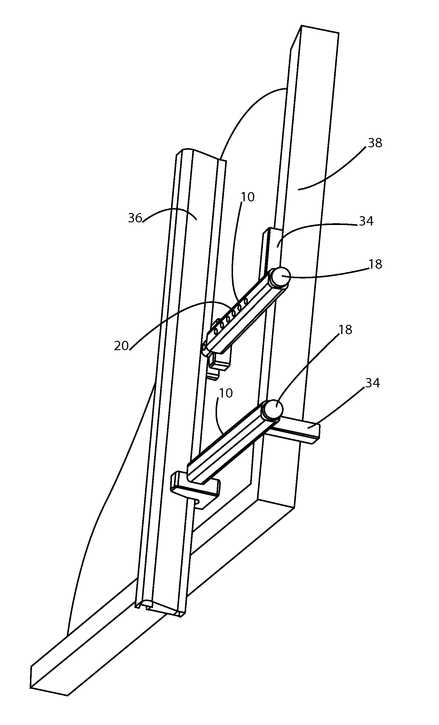
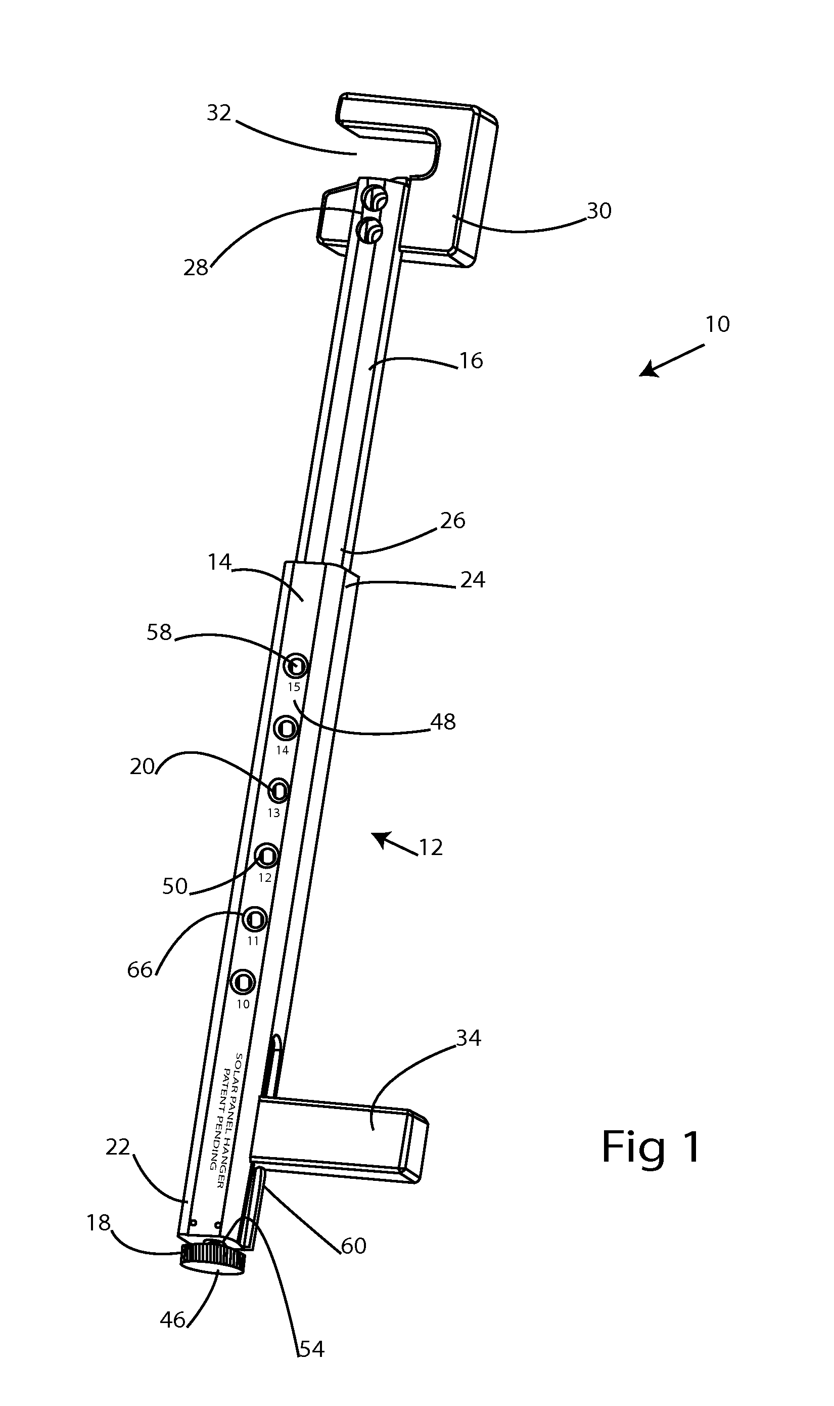
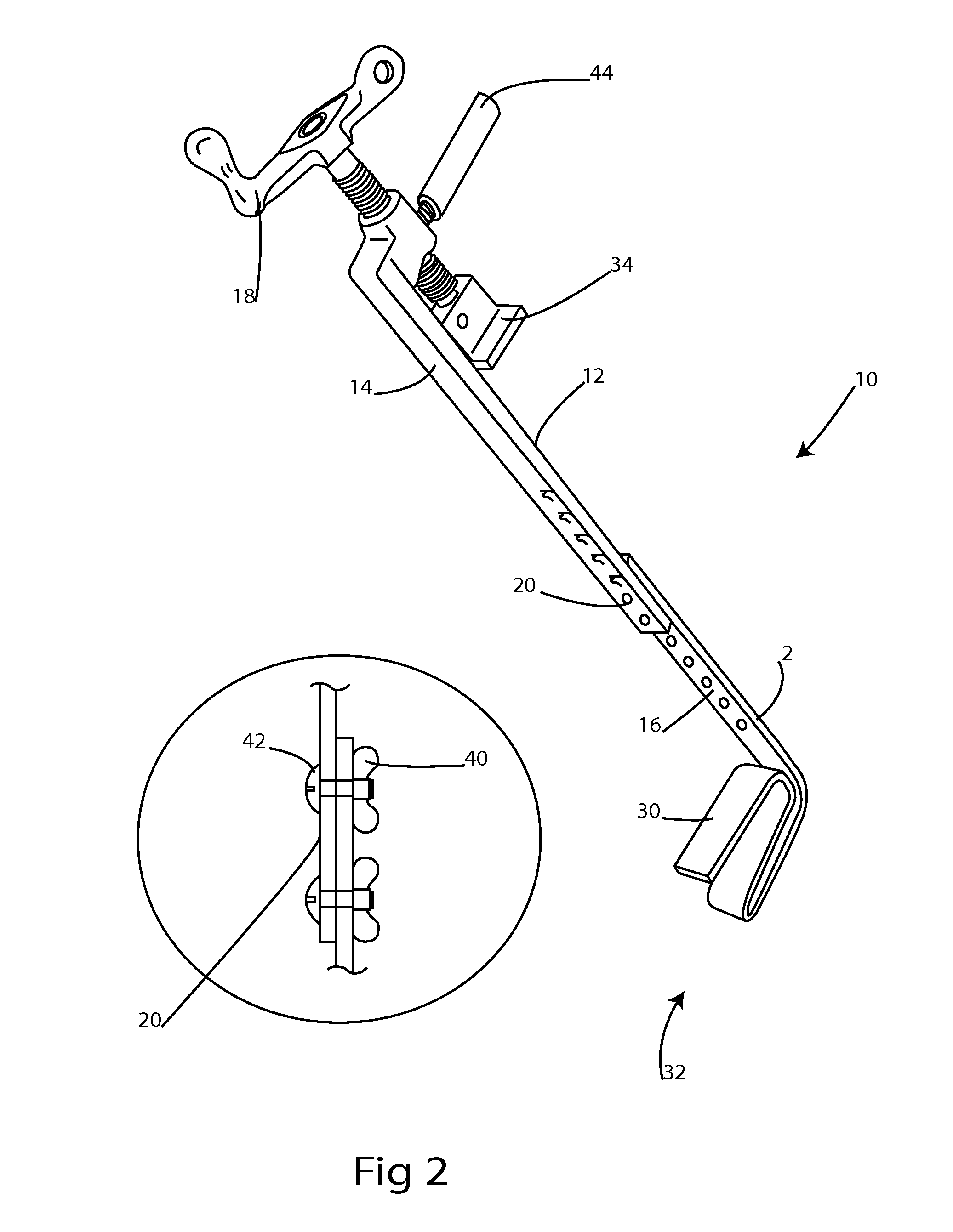
[0024]Referring now to the figures, FIG. 1 shows one embodiment of the solar installation tool. The solar installation tool is referred to as 10 in the figures, and in the embodiment shown in FIG. 1 includes a tool body 12, outer tube 14, and inner tube 16. The inner tube telescopes out from the outer tube, and the installation tool 10 includes a coarse adjustment 20 in the form of hole...


PUM


Abstract

A solar panel installation tool, with coarse and fine position adjustment. The tool fits on a mounting rail installed on a roof, and supports the solar panel along its bottom side. A panel support bracket on the tool is adjusted to align the solar panel with the roof edge. The tool can be removed after the solar panel is bolted into place on the rack.

Description

PRIORITY / CROSS-REFERENCE TO RELATED APPLICATIONS[0001]This application claims the benefit of U.S. Provisional Application No. 62 / 060,908, filed Oct. 7, 2014 the disclosure of which is incorporated by reference.TECHNICAL FIELD[0002]The presently disclosed technology relates to a tool for use in mounting solar panels, and more specifically, a tool for mounting solar panels so that the bottom edges of solar panels align perfectly.BACKGROUND[0003]A common way to mount solar panels on a structure is by using mounting rails. The structure can be a steel frame which stands alone on posts, or the structure can be the roof of a building, the wall of a building, or the roof or walls of mobile structures such as RVs or vehicles. The example of solar panels which are mounted on the roof of a structure will be used for convenience, but is not meant to limit the claimed technology. Solar panels are typically rectangular and are mounted on mounting rails. The mounting rails are generally not perfe...

Claims


Application Information

Patent Timeline
Patent Type & Authority Applications(United States)
IPC IPC(8): F24J2/52B25B11/00
CPCF24J2/5205F24J2002/5281F24J2002/5273B25B11/00F24S25/30B25B11/02F24S2025/01F24S2025/014Y02B10/20Y02E10/47
Inventor KING, KEVIN
Owner KING KEVIN
Why Eureka
Try Eureka