Control valve

a control valve and valve element technology, applied in the field of control valves, can solve problems such as deteriorating actuation responsiveness, and achieve the effects of suppressing control hunting, enhancing actuation responsiveness of valve elements, and relatively small sliding resistan

Inactive Publication Date: 2016-04-07
TGK
View PDF3 Cites 10 Cited by
  • Summary
  • Abstract
  • Description
  • Claims
  • Application Information

AI Technical Summary

Benefits of technology

[0010]The present invention has been made in view of the foregoing problems, and a purpose thereof is to provide a control valve capable of effectively suppressing both the vibration sound during the actuation of a valve element and the control hunting.
[0012]By employing this embodiment, the magnitude of the sliding resistance affected to the valve element is varied by the position of the valve element in the direction of axis line. Specifically, the sliding resistance can be varied according to the opening degree of the valve element. This enables the sliding resistance to be relatively small in a valve opening degree region, where it is desired that the actuation responsiveness of the valve element be enhanced and the control hunting be suppressed, and also enables the sliding resistance to be relatively large in a valve opening degree region, where the vibration sound tends to be larger. As a result, a control valve capable of effectively suppressing both the vibration sound during the actuation of the valve element and the control hunting can be provided.

Problems solved by technology

However, an increased sliding resistance may increase the hysteresis during an opening / closing actuation of the valve element and thereby deteriorate the actuation responsiveness thereof; this may possibly cause a control hunting.

Method used


Image

  • Control valve
  • Control valve
  • Control valve

Examples


first embodiment

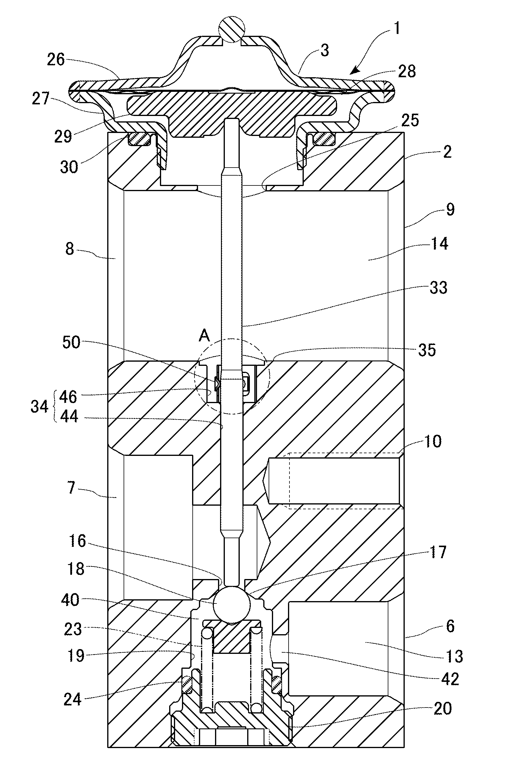
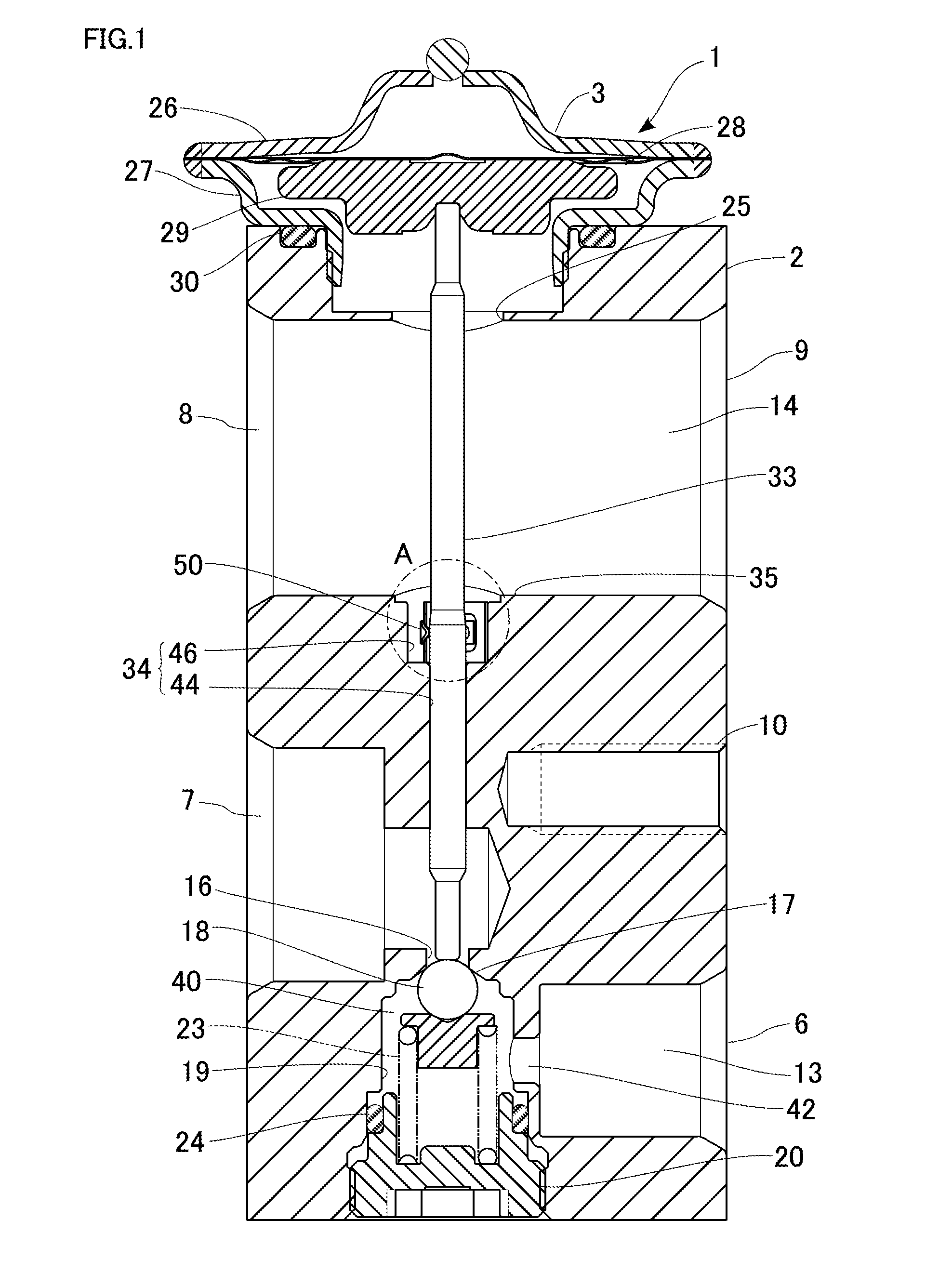
[0024]The present embodiment is a constructive reduction to practice of the present invention where an expansion valve according to the preferred embodiments is used as a thermostatic expansion valve applied to a refrigeration cycle of an automotive air conditioner. The refrigeration cycle in the automotive air conditioner is configured by including a compressor, a condenser, a receiver, an expansion valve, and an evaporator. Here, the compressor compresses a circulating refrigerant. The condenser condenses the compressed refrigerant. The receiver separates the condensed refrigerant into a gas and a liquid. The expansion valve throttles and expands the separated liquid refrigerant and delivers it by turning it into a spray. The evaporator evaporates the misty refrigerant and thereby cools the air inside a vehicle's passenger compartment by the evaporative latent heat. A detailed description of each component except for the expansion valve in this refrigeration cycle is omitted in th...

second embodiment

[0057]An expansion valve according to a second embodiment differs from the first embodiment in the structure of the sliding mechanism. FIG. 7 is a cross-sectional view of the expansion valve according to the second embodiment. FIGS. 8A to 8D are each an enlarged view of a region B encircled in FIG. 7. FIG. 8A shows a state where a valve element is in the valve-closed position or in a position close thereto (a slightly open position). FIG. 8B shows a state where the valve element is in the fully open position or in a position close thereto. FIG. 8C is an enlarged view of a region C encircled in FIG. 8A, and FIG. 8D is an enlarged view of a region C encircled in FIG. 8B.

[0058]As shown in FIG. 7, in an expansion valve 201, an insertion hole 234 is so formed as to run through a partition wall 35 in a body 202, and a shaft 233 is inserted into the insertion hole 234. The shaft 233 is cylindrical in shape across the entire length thereof with a constant cross section, and is slidably supp...


PUM


Abstract

An expansion valve includes a shaft one end side of which connects to a power element and the other end side of which connects to a valve element, the shaft transmitting the drive force, generated by the power element in a direction of axis line, to the valve element, and a sliding mechanism that applies a sliding resistance to the actuation of the valve element. The sliding mechanism is configured such that the magnitude of the sliding resistance affected to the valve element is varied by the position of the valve element in the direction of axis line in the body.

Description

CLAIM OF PRIORITY[0001]This application claims priority to Japanese Patent Application No. 2014-203378, filed Oct. 1, 2014, and is incorporated herein by reference.BACKGROUND OF THE INVENTION[0002]1. Field of the Invention[0003]The present invention relates to a control valve and, more particularly to a structure of a vibration-proof spring suitable in preventing the vibration of an actuating section of the control valve.[0004]2. Description of the Related Art[0005]A refrigeration cycle in an automotive air conditioner is generally configured such that the refrigeration cycle includes a compressor, a condenser, a receiver, an expansion valve, and an evaporator. The compressor compresses a circulating refrigerant. The condenser condenses the compressed refrigerant. The receiver separates the condensed refrigerant into a gas and a liquid. The expansion valve throttles and expands the separated liquid refrigerant and delivers it by turning it into a spray. Then the evaporator evaporate...

Claims


Application Information

Patent Timeline
Patent Type & Authority Applications(United States)
IPC IPC(8): F25B41/06F25B49/02F16K27/02
CPCF25B41/062F25B49/02F16K27/02F25B2341/0683F25B2500/13F25B41/335
Inventor KANEKO, TAKESHI
Owner TGK
Why Eureka
Try Eureka