
Chain transmission device

a transmission device and chain technology, applied in the direction of belts/chains/gearrings, mechanical instruments, belts/chains/gearrings, etc., can solve the problem of large transmission loss of torque, and achieve the effect of guiding the chain very quietly and reducing the vibration of the chain

Inactive Publication Date: 2018-03-13
NTN CORP
View PDF27 Cites 0 Cited by
  • Summary
  • Abstract
  • Description
  • Claims
  • Application Information

AI Technical Summary

Benefits of technology

The chain transmission device described in this patent prevents vibration and noise by keeping the excitation frequency away from the natural frequency of the chain. This allows for quieter operation of the device.

Problems solved by technology

However, since such sliding-type chain guides are in sliding contact with the chain, there is the problem that the resistance to the movement of the chain is large so that the transmission loss of torque is large.

Method used


Image

  • Chain transmission device
  • Chain transmission device
  • Chain transmission device

Examples


Embodiment Construction

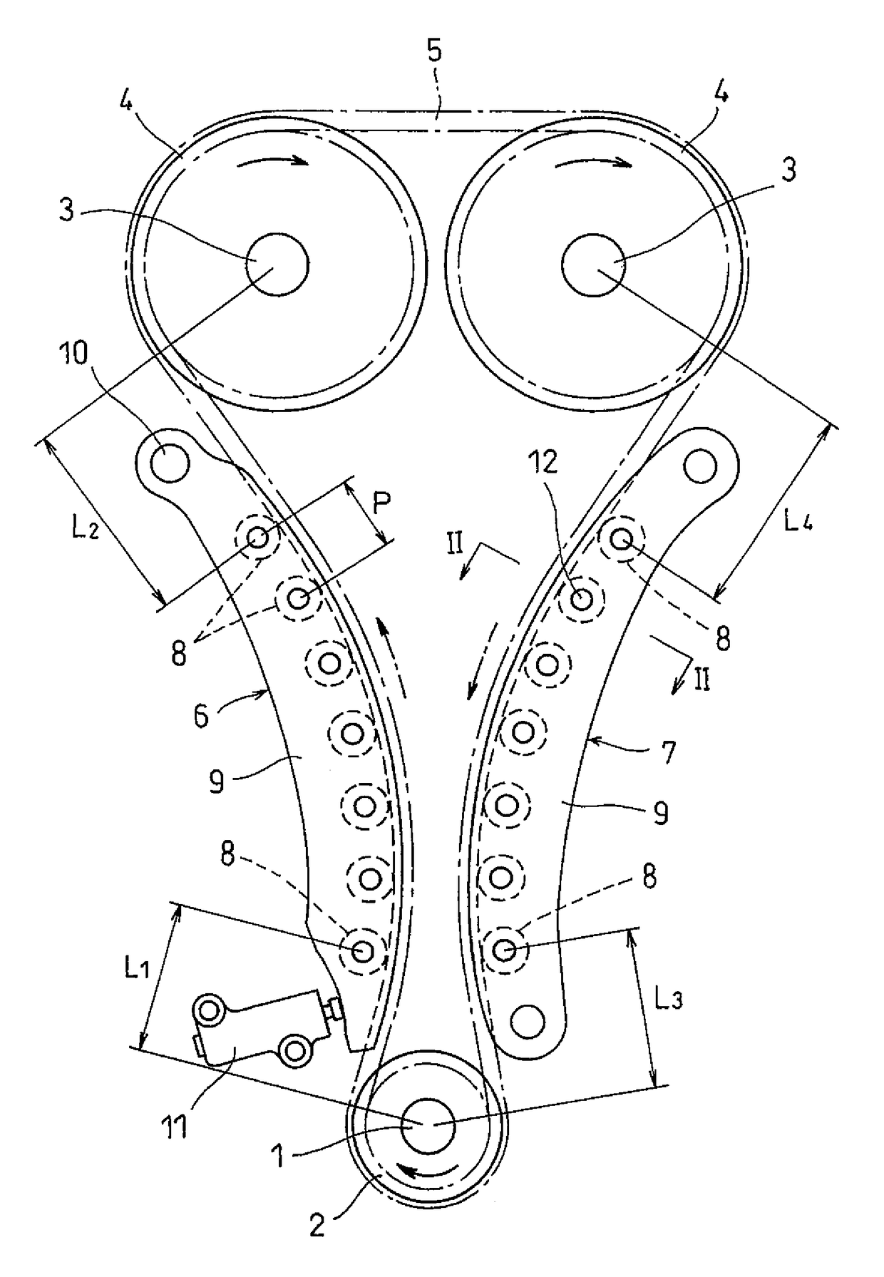
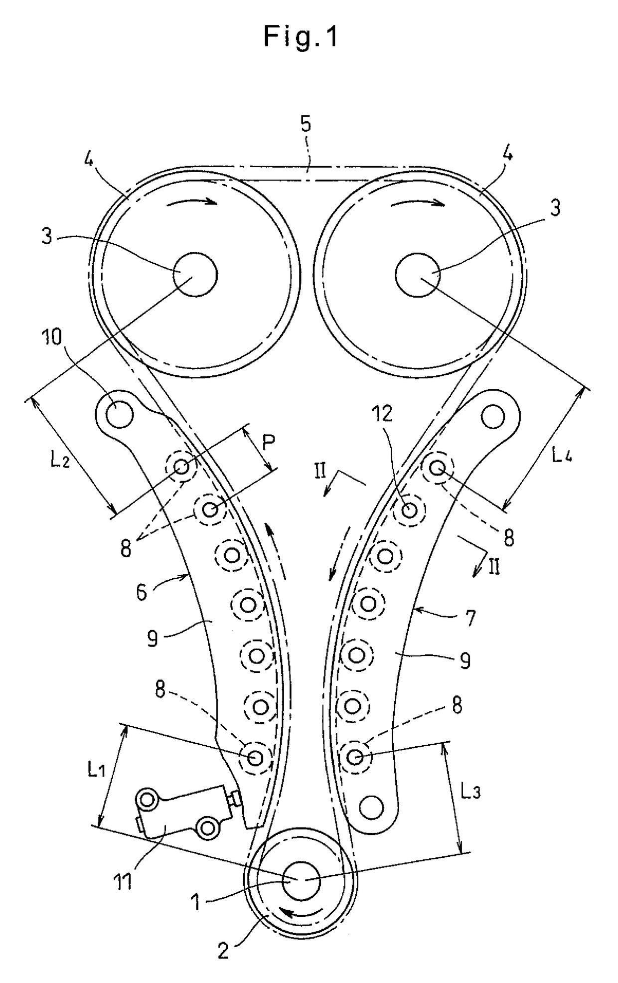
[0025]FIG. 1 illustrates a chain transmission device according to the embodiment of the present invention. This chain transmission device includes a crank sprocket 2 attached to a crankshaft 1 of an engine, left and right cam sprockets 4 attached to respective camshafts 3, and a chain 5 trained around the crank sprocket 2 and the cam sprockets 4. The rotation of the crankshaft 1 is transmitted to the camshafts 3 by means of the chain 5 so as to rotate the camshafts 3, thereby opening and closing valves of combustion chambers (not shown).

[0026]While the engine is operating, the crankshaft 1 always rotates in the same direction (clockwise direction in FIG. 1). While the crankshaft 1 is rotating in this direction, the portion of the chain 5 moving from the crank sprocket 2 toward the left cam sprocket 4 (left portion of the chain 5 in FIG. 1) becomes loose (this portion is therefore called “loose side”), while the portion of the chain 5 moving from the (right) cam sprocket 4 toward the...


PUM


Abstract

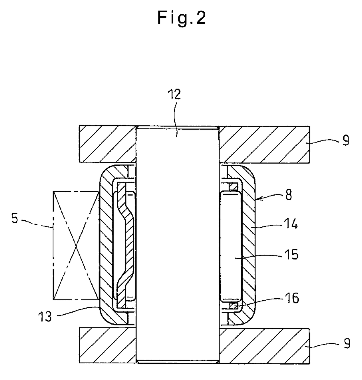
A chain transmission device includes chain guides capable of guiding a chain. The chain guides include a plurality of spaced apart rollers for guiding the chain, and a distance L (m) between contact points of a trained portion of the chain is set to satisfy the following inequality:L<12⁢ωMAX⁢Tρ,where ωMAX is a maximum excitation frequency (Hz) from a crankshaft, ρ is a mass of the chain per unit length (kg / m), and T is a time-average tension of the chain (N).

Description

TECHNICAL FIELD[0001]The present invention mainly relates to a chain transmission device in which the rotation of a crankshaft of an automobile engine is transmitted to camshafts.BACKGROUND ART[0002]In an automobile engine, the rotation of a crankshaft is transmitted to camshafts by means of a timing chain made of iron (hereinafter, simply referred to as a “chain”) so as to rotate the camshafts, thereby opening and closing valves of combustion chambers.[0003]Chain transmission devices are used to drive such camshafts. Many of such chain transmission devices include a crank sprocket attached to a crankshaft of an engine, cam sprockets attached to respective camshafts of the engine, a chain trained around the crank sprocket and the cam sprockets, a loose side chain guide arranged so as to guide the portion of the chain configured to move from the crank sprocket toward one of the cam sprockets, and a tension side chain guide arranged so as to guide the portion of the chain configured t...

Claims


Application Information

Patent Timeline
Patent Type & Authority Patents(United States)
IPC IPC(8): F16H7/20F16H7/06F16H7/18F16H7/08
CPCF16H7/20F16H7/06F16H7/18F16H2007/0893F16H2007/0865F16H2007/0872
Inventor KATO, AKIOYAMASHITA, TAKAHIROHASEGAWA, HISATAKA
Owner NTN CORP
Learn More