
Analysis of a structure modeled with intraply interface elements

a technology of intraply interface elements and structural finite element, applied in the direction of instruments, design optimisation/simulation, computation using non-denominational number representation, etc., can solve the problems of inability to compare the way to deal with intra-laminar failure, the accuracy of simulations must be demonstrated, and the tools of pfa have yet to overcome, so as to improve the ability of simulation, increase the likelihood, and natural configuration

Active Publication Date: 2016-04-07
THE BOEING CO
View PDF4 Cites 6 Cited by
  • Summary
  • Abstract
  • Description
  • Claims
  • Application Information

AI Technical Summary

Benefits of technology

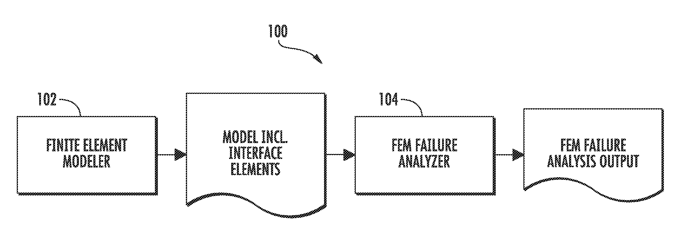
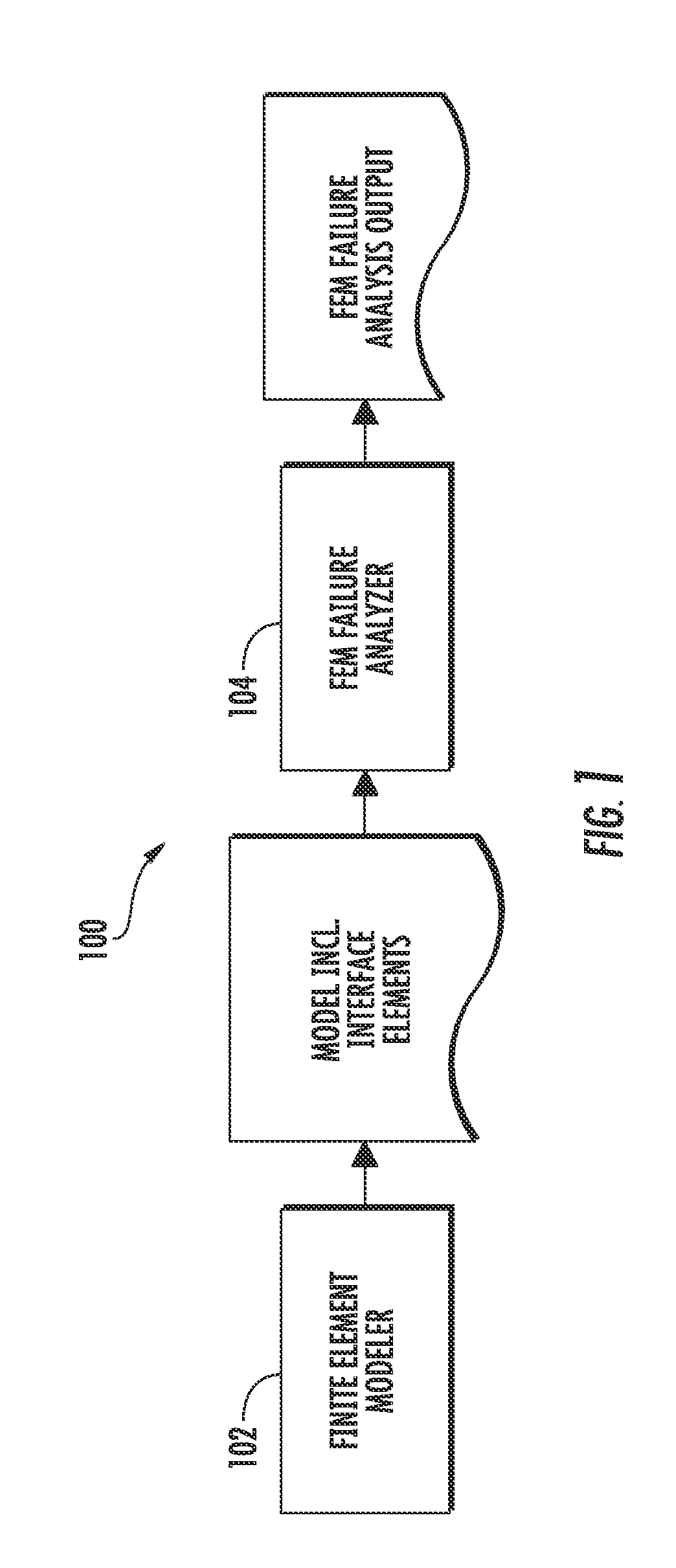
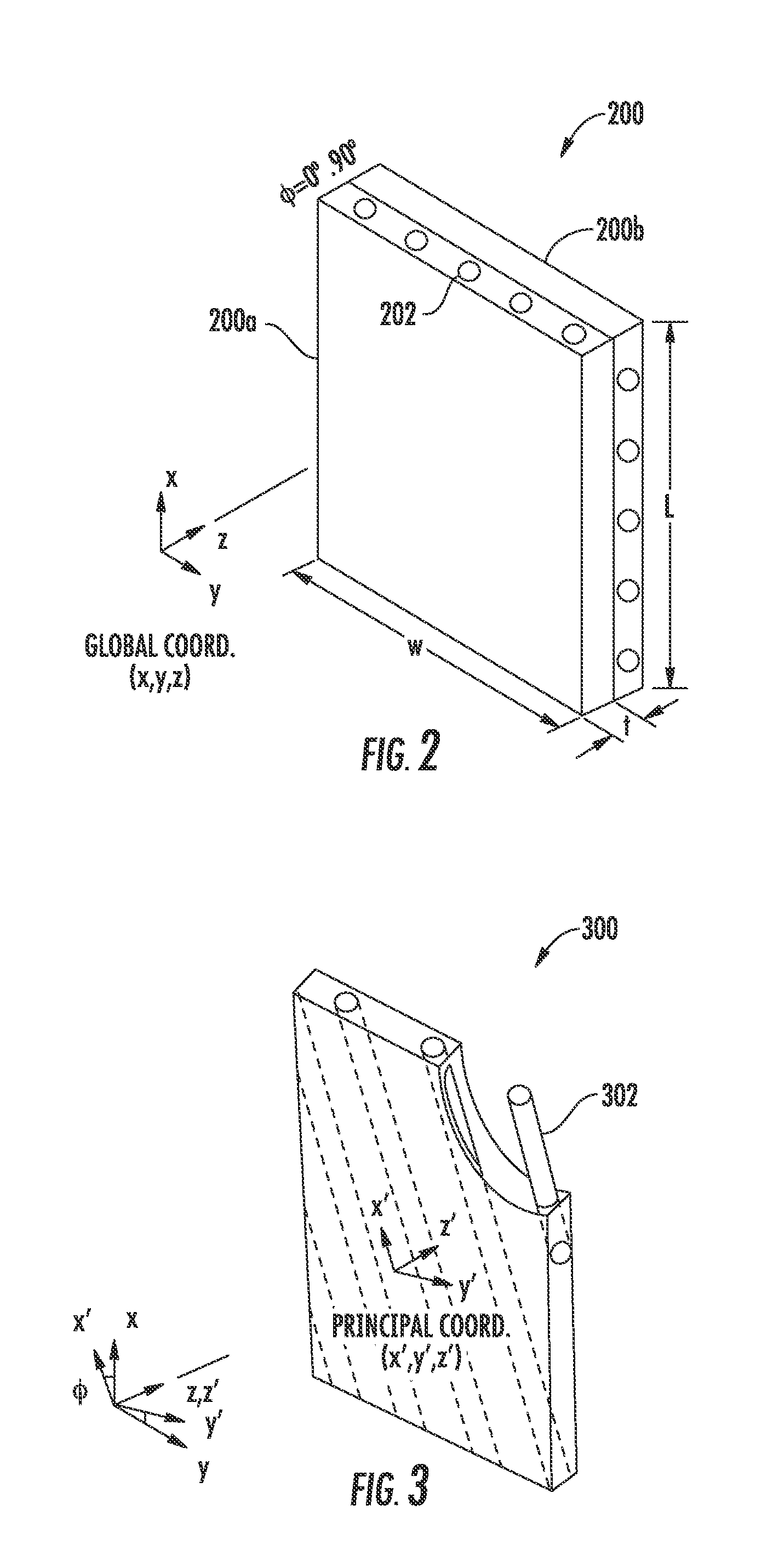
The present invention provides an improved way to analyze structures using a method called finite element method (FEM) analysis. It does this by using a meshing scheme that separates the main types of failure modes in the structure, namely in the matrix and in the fiber. The method also aligns the ply-level finite elements with the natural direction of the fiber and adds additional elements within the plies to capture potential failure modes. This results in a more natural configuration and an increased likelihood of capturing the failure modes that may affect the final strength prediction.

Problems solved by technology

But one of the challenges that these PFA tools have yet to overcome is that accuracy of the simulations must be demonstrated for a broad design space, test type and loading conditions.
But there is no comparable way to deal with intra-laminar failure.

Method used


Image

  • Analysis of a structure modeled with intraply interface elements
  • Analysis of a structure modeled with intraply interface elements
  • Analysis of a structure modeled with intraply interface elements

Examples


Embodiment Construction

[0023]Some implementations of the present disclosure will now be described more fully hereinafter with reference to the accompanying drawings, in which some, but not all implementations of the disclosure are shown. Indeed, various implementations of the disclosure may be embodied in many different forms and should not be construed as limited to the implementations set forth herein; rather, these example implementations are provided so that this disclosure will be thorough and complete, and will fully convey the scope of the disclosure to those skilled in the art. For example, unless otherwise indicated, reference something as being a first, second or the like should not be construed to imply a particular order. Also, something may be described as being above something else (unless otherwise indicated) may instead be below, and vice versa; and similarly, something described as being to the left of something else may instead be to the right, and vice versa. Like reference numerals ref...


PUM


Abstract

A method of analyzing a structure includes producing a finite element model of the structure having fibers embedded therein, and including one or more plies. This may include performing a discretization of a digital model of the structure in which each ply of the one or more plies is represented by a mesh of finite elements aligned with a direction of uni-directional fibers embedded in the ply. Producing the finite element model may also include adding a fiber-aligned intraply interface element between selected adjacent finite elements in the mesh of each ply to capture potential intraply failure modes. And the method may include performing a finite element method (FEM) failure analysis of the finite element model under a load, with the FEM failure analysis producing an output that indicates an extent of any of the potential intraply failure modes that result from the finite element model under the load.

Description

TECHNOLOGICAL FIELD[0001]The present disclosure relates generally to structural finite element analysis and, in particular, to progressive failure analysis of a structure modeled with intraply interface elements.BACKGROUND[0002]Advances in software-based tools such as progressive failure analysis (PFA) tools to predict structural failure of laminated composite parts have enabled replacing expensive tests with simulations. But one of the challenges that these PFA tools have yet to overcome is that accuracy of the simulations must be demonstrated for a broad design space, test type and loading conditions. This includes correctly idealizing failure modes known to affect the failure load of a coupon during testing.[0003]As an example, consider composites of unidirectional tape plies, a common material ply in which fibers are aligned in a single direction and imbedded in a matrix of epoxy resin. Individual plies with unique orientations are stacked together and cured to form a single lam...

Claims


Application Information

Patent Timeline
Patent Type & Authority Applications(United States)
IPC IPC(8): G06F17/50
CPCG06F17/5018G06F30/23G06F2113/26
Inventor PENA, GERARDOGAVIN, JEFFREY B.BAUCUM, JEFFREY P.
Owner THE BOEING CO
Learn More