Information processing system and information processing method

a technology which is applied in the field of information processing system and information processing method, can solve the problems of affecting the accuracy of recognizing a subject, difficult to match corresponding regions appropriately, and difficult to derive accurate parallax values

Active Publication Date: 2016-04-07
RICOH KK
View PDF1 Cites 11 Cited by
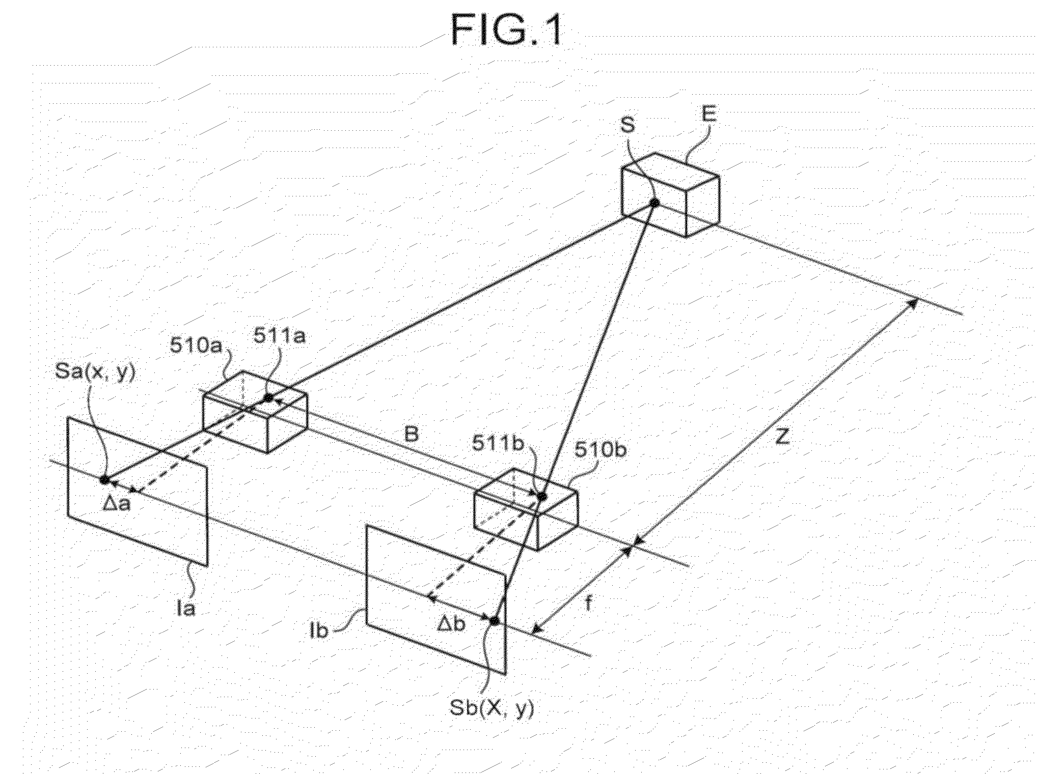
  • Summary
  • Abstract
  • Description
  • Claims
  • Application Information

AI Technical Summary

Benefits of technology

[0010]It is an object of the present invention to at least partially solve the problems in the conventional technology.
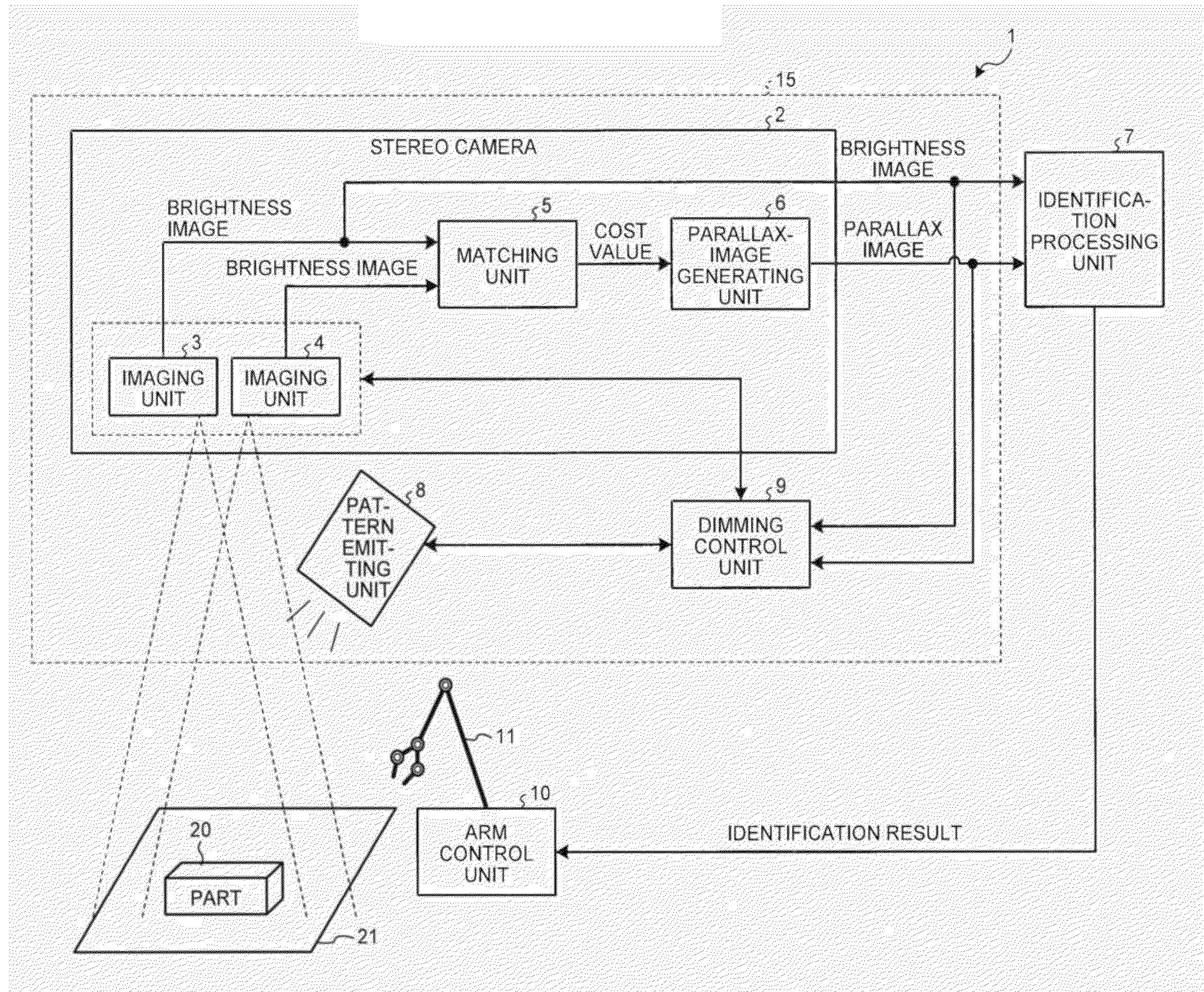
[0011]According to the present invention, there is provided an information processing system, comprising: a light emitting unit that irradiates pattern light having a specific pattern to a subject to form a texture on the subject; an imaging unit that captures the subject on which the texture is formed; a deriving unit that derives distance information to the subject based on an image captured by the imaging unit; an analyzing unit that analyzes whether or not an image abnormality is present in either one of the captured image and an image based on the distance information; and a dimming unit that performs dimming control when the analyzing unit analyzes that the image abnormality is present.
[0012]The present invention also provides an information processing system comprising: a light emitting unit that irradiates a pattern light having a specific pattern to a subject to form a texture on the subject; an imaging unit that captures the subject on which the texture is formed; a deriving unit that derives distance information to the subject based on a image captured by the imaging unit; a setting unit that sets information about the subject; and a dimming unit that performs dimming control based on the information about the subject set by the setting unit.
[0013]The present invention also provides an information processing method, comprising irradiating pattern light having a specific pattern to a subject to form a texture on the subject; capturing the subject on which the texture is formed; deriving distance information to the subject based on the captured image; analyzing whether or not an image abnormality is present in either one of the captured image and an image based on the distance information; and performing dimming control when analyzed that the image abnormality is present. The above and other objects, features, advantages and technical and industrial significance of this invention will be better understood by reading the following detailed description of presently preferred embodiments of the invention, when considered in connection with the accompanying drawings.

Problems solved by technology

However, if a texture is weak in an image in which an object being a subject is captured, when the stereo matching process described above is performed, it is difficult to match corresponding regions appropriately, and it is difficult to derive an accurate parallax value.
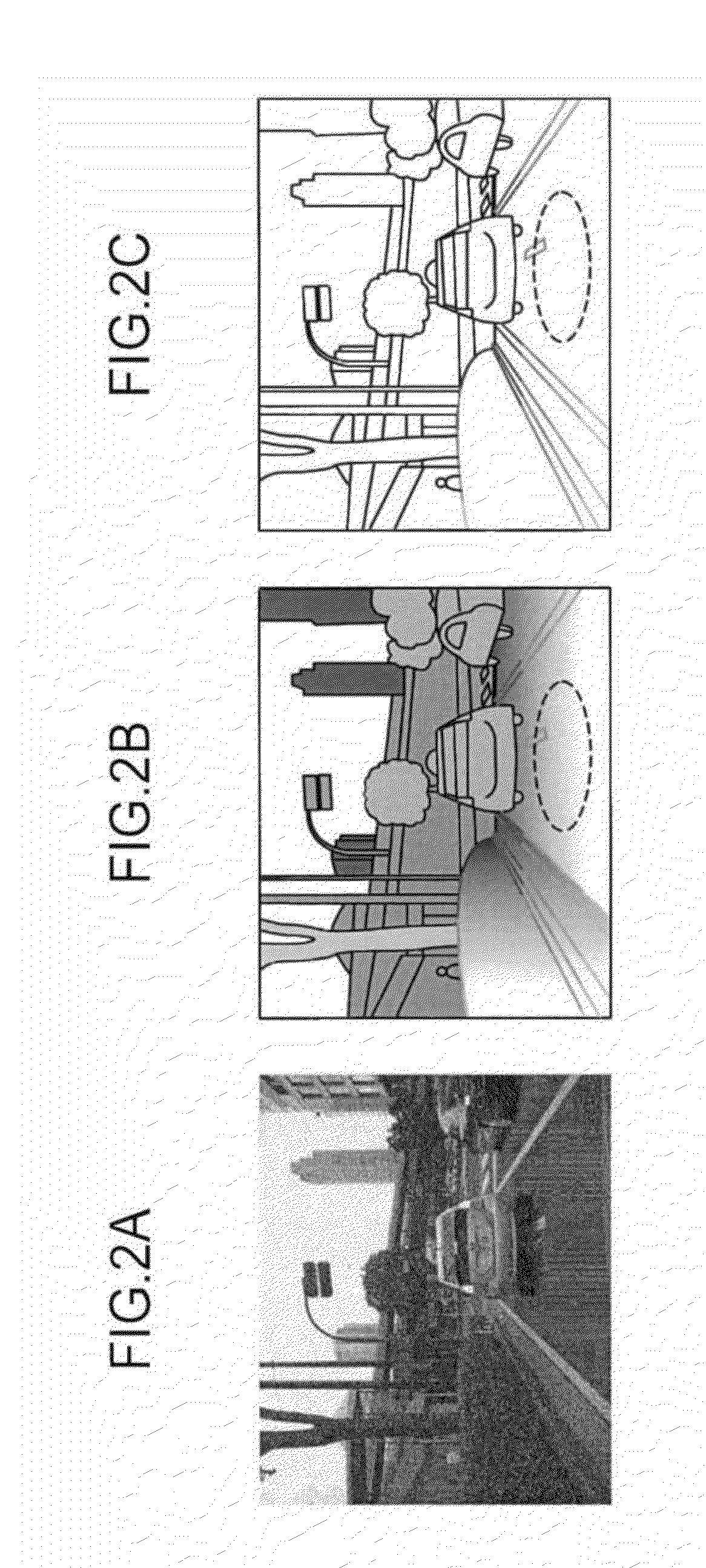
However, in the technique described in the above patent literature, there is a possibility that accuracy in recognizing a subject is affected, for example, when an abnormal condition, such as a state having blocked-out shadows, a saturated state with blown-out highlights, and reflection of light from a light emitting unit, occurs in an image depending on a condition of placement of a subject.

Method used


Image

  • Information processing system and information processing method
  • Information processing system and information processing method
  • Information processing system and information processing method

Examples


first modification

[0185

[0186]FIG. 22 illustrates one example of a hardware configuration of a parallax-value deriving system according to a first modification of the present embodiment. Referring to FIG. 22, a parallax-value deriving system 15a according to the present modification is explained mainly about a point that is different from the parallax-value deriving system 15 of the present embodiment described above. Because the stereo camera 2 and the dimming control unit 9 shown in FIG. 22 are the same as those shown in FIG. 8 of the embodiment described above, the same reference symbols are given and explanations thereof are omitted herein.

[0187]As shown in FIG. 22, the parallax-value deriving system 15a according to the present modification includes the stereo camera 2, a pattern emitting unit 8a, the dimming control unit 9, and a texture transmitting unit 12 (transmitting unit). Among these, the pattern emitting unit 8a is a device that irradiates pattern light having a special pattern to the pa...

second modification

[0191

[0192]FIG. 23 is a diagram illustrating one example of functional blocks of a stereo camera of a second modification of the present embodiment. Referring to FIG. 23, a stereo camera 2a of the present modification is explained mainly about a point different from the stereo camera 2 of the above embodiment. Because the imaging units 3 and 4, the matching unit 5, and the parallax-image generating unit 6 shown in FIG. 23 are the same as those shown in FIG. 11 of the embodiment described above, the same reference symbols are given and explanation thereof is omitted herein.

[0193]As shown in FIG. 23, the stereo camera 2a includes the imaging units 3 and 4, preprocessing units 13 and 14 (first preprocessing unit, second preprocessing unit), the matching unit 5, and the parallax-image generating unit 6.

[0194]The preprocessing units 13 and 14 are devices that perform image processing, such as distortion correction and dynamic range expansion, on brightness images generated by the imaging...

third modification

[0196

[0197]FIG. 24 is an explanatory diagram for a case of calculating a corresponding pixel in a comparison image that corresponds to a reference pixel in a reference image in a parallax-value deriving system according to a third modification of the present embodiment. With Reference to FIG. 24, operation of the parallax-value deriving system according to the present modification is explained mainly about a point different from the parallax-value deriving system 15 of the embodiment described above.

[0198]As shown in FIG. 24, it is considered a case in which a saturated region 22 is formed in a part region 20b that is a portion in which a part is imaged in a comparison image Ia_2 (or reference image Ib_2) due to reflection of the part. When it is performed searching (in a direction of arrow in FIG. 24) to calculate the cost value C from a candidate region q1 in the saturated region 22 of the comparison image Ia_2 with respect to a reference region p1 in the saturated region 22 of th...


PUM


Abstract

An information processing system comprises: a light emitting unit that irradiates pattern light having a specific pattern to a subject to form a texture on the subject; an imaging unit that captures the subject on which the texture is formed; a deriving unit that derives distance information to the subject based on an image captured by the imaging unit; an analyzing unit that analyzes whether or not an image abnormality is present in either one of the captured image and an image based on the distance information; and a dimming unit that performs dimming control when the analyzing unit analyzes that the image abnormality is present.

Description

CROSS-REFERENCE TO RELATED APPLICATIONS[0001]The present application claims priority to and incorporates by reference the entire contents of Japanese Patent Application No. 2014-204693 filed in Japan on Oct. 3, 2014 and Japanese Patent Application No. 2015-000389 filed in Japan on Jan. 5, 2015.BACKGROUND OF THE INVENTION[0002]1. Field of the Invention[0003]The present invention relates to an information processing system and an information processing method.[0004]2. Description of the Related Art[0005]Recent years, as a technique to measure a distance to an object, a stereo matching process using the triangulation principle with a stereo camera that includes two cameras has been used. The stereo matching process is a process of calculating a distance between a stereo camera and an object included in an image based on a parallax value obtained by matching corresponding regions in a reference image that is captured by one camera and in a comparison image that is captured by the other ...

Claims


Application Information

Patent Timeline
Patent Type & Authority Applications(United States)
IPC IPC(8): G06T7/00H04N13/02H04N5/225H04N13/00H04N13/239
CPCG06T7/0075G06T7/0059H04N2013/0081H04N13/0239H04N5/2256H04N13/0022G01B11/2513G06T7/529G06T7/593H04N13/239H04N13/128G06T7/44H04N23/56
Inventor SEKIGUCHI, HIROYOSHIKOYAMA, TERUNORIYAMADA, KAZUYOSHI
Owner RICOH KK
Why Eureka
Try Eureka