Image deformation device

Active Publication Date: 2016-04-07
KONICA MINOLTA INC
View PDF0 Cites 0 Cited by
  • Summary
  • Abstract
  • Description
  • Claims
  • Application Information

AI Technical Summary

Benefits of technology

The objective of the patent is to create an image deformation device that can deform image data accurately and precisely while keeping the memory usage low. This device can also be used to correct the position of each pixel in the image.

Problems solved by technology

However, because the actual deformation (distortion) of the output image, which is caused in an image output device, is complicated due to a plurality of factors, in order to correct the above deformation, a complicated deformation process shown in FIG. 14 is required.
Therefore, it is not possible to completely eliminate the deformation of the output image by a simple correction, such as the rotation, the enlargement, the reduction or the like, which can be carried out by using the above calculation.
However, in this case, because the positional correction amount for each pixel is held, an enormous memory for storing the positional correction amount is required.
As a result, the image deformation device becomes extremely expensive, or it is actually impossible to include the SRAM in the image processing LSI.
Therefore, although the technology disclosed in Japanese Patent Application Publication No. 2009-122763 is applied, it is required to largely thin the data.
As a result, the precision of the positional correction is significantly deteriorated.

Method used


Image

  • Image deformation device
  • Image deformation device
  • Image deformation device

Examples


first embodiment

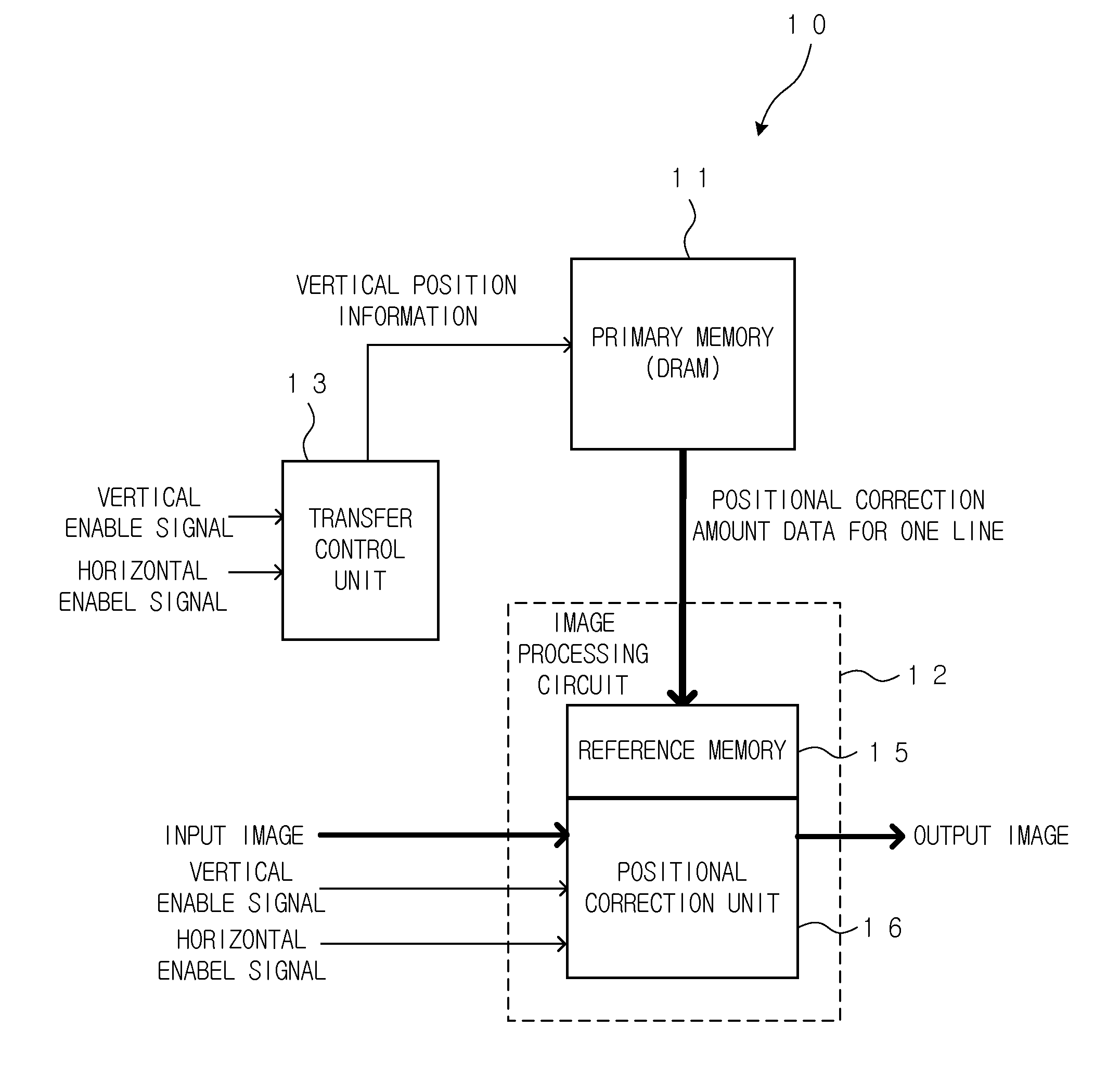
[0042]FIG. 1 is a block diagram showing the schematic configuration of the image deformation device 10 according to the first embodiment. The image deformation device 10 has the function for generating an output image in which the position of each pixel in an input image is changed to the intended position of each pixel.

[0043]The input image to be processed is an image having the dot matrix form in which the pixels are arranged in the first direction and in the second direction which is perpendicular to the first direction. Further, the output image is also an image having the dot matrix form in which the pixels are arranged in the first direction and in the second direction which is perpendicular to the first direction. In this case, the first direction is the horizontal direction and the second direction is the vertical direction.

[0044]For example, the image deformation device 10 is provided on the previous stage or the like of the laser unit of the laser printer. The image signal...

second embodiment

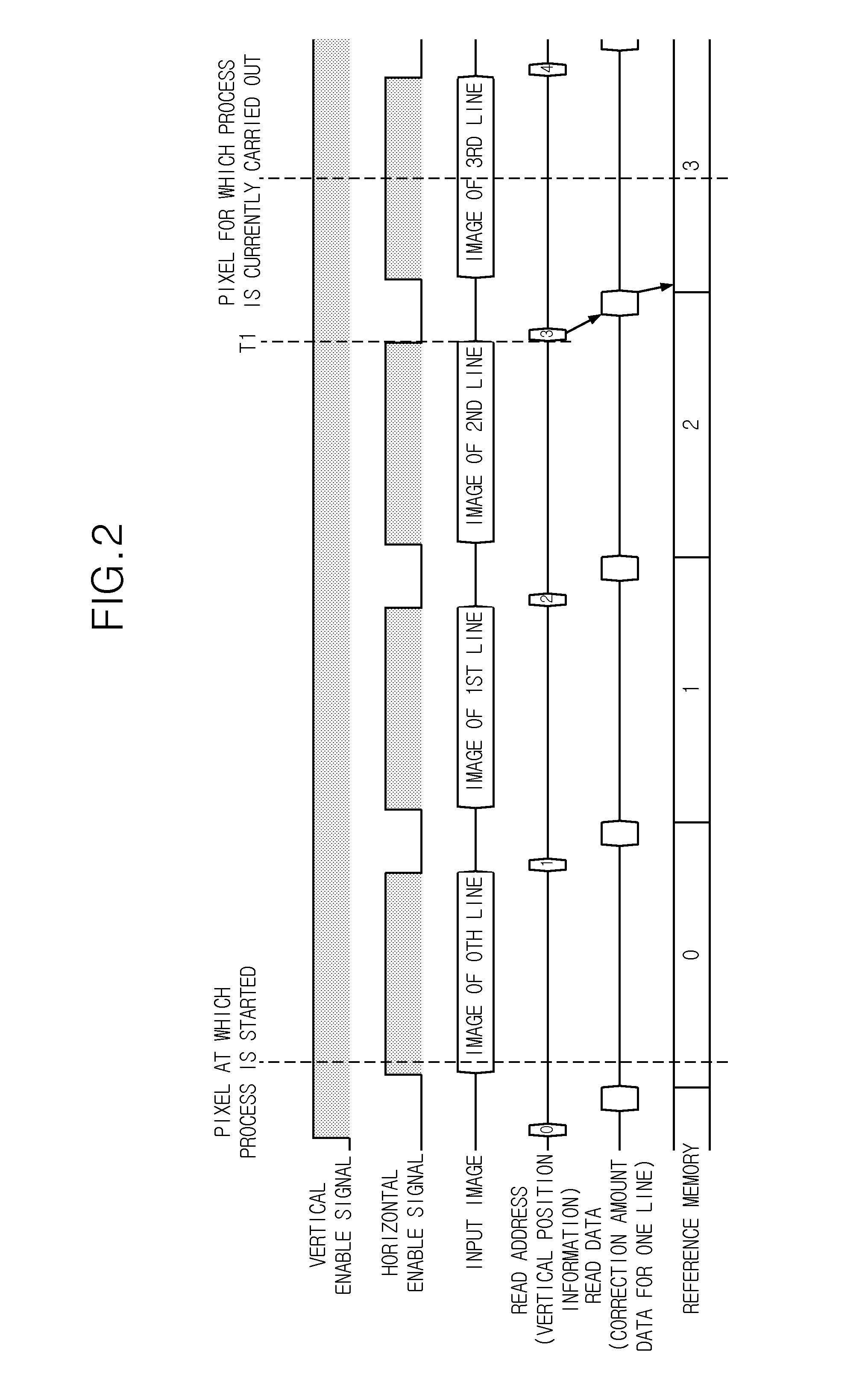
[0063]In the first embodiment, the positional correction amount data held in the reference memory 15 is updated by transferring the positional correction amount data from the primary memory 11 to the reference memory 15 at the timing immediately before the staring of the positional correction process for each line (during the invalid time region). However, in case that the time period (the invalid time region) between the valid time region (in which the horizontal enable signal is ON (effective)) for one line and the valid time region for the next line is extremely short, or in case that the transfer speed of the data from the DRAM is not sufficient, all of the positional correction amount data for one line cannot be transferred during the above invalid time region. As a result, the positional correction process cannot be normally carried out. The second embodiment is one for solving the above problem.

[0064]FIG. 5 shows the configuration of the image deformation device 20 according ...

third embodiment

[0078]In the first and the second embodiments, the positional correction amount data for one page or a plurality of pages is stored in the primary memory 11 or 21 which is the DRAM. However, because the memory size for which the positional correction amount data can be stored in the DRAM as the primary memory is limited, there are some cases in which the positional correction amount data for one page cannot be stored. Therefore, in the third embodiment, as the primary memory, a main memory or a hard disk drive which can secure the large capacity is used.

[0079]Because there are some cases in which the readout of the data from the hard disk drive is delayed as compared with the DRAM, the transfer of the data is too slow in the method in which the positional correction amount data is directly transferred from the hard disk drive to the reference memory 15 in the image processing circuit 12. Even though the first reference memory 26 and the second reference memory 27 are used alternatel...


PUM


Abstract

Disclosed is an image deformation device, including: a primary memory in which a positional correction amount data for each pixel, is stored; a reference memory having a smaller storing area than the primary memory; a transfer unit configured to transfer the positional correction amount data stored in the primary memory to the reference memory separately in multiple times; and a positional correction unit configured to carry out a positional correction process, wherein the transfer unit transfers the positional correction amount data according to the predetermined order and a progress of the positional correction process in the positional correction unit so that the positional correction amount data for one pixel has been already stored in the reference memory when the positional correction unit corrects the position of the one pixel.

Description

BACKGROUND OF THE INVENTION[0001]1. Field of the Invention[0002]The present invention relates to an image deformation device for deforming an input image by correcting the pixel position of each pixel in the input image.[0003]2. Description of Related Art[0004]In an image output device, such as a printer using an electrophotographic process, or the like, because an output image is deformed due to the fixing and / or the irregularity of the paper feeding, the deformation of the output image is suppressed by deforming the image data in a direction opposite to the deforming direction.[0005]In case that an image deformation process is a simple correcting process, such as the enlargement (or the reduction) shown in FIG. 12, the rotation shown in FIG. 13 or the like, by inputting the parameter, such as the rotation angle, the magnification or the like, to the deformation processing unit, the deformation processing unit can calculate the positional shift amount of each pixel based on the par...

Claims


Application Information

Patent Timeline
IPC IPC(8): H04N1/387H04N1/32H04N1/12H04N1/21
CPCH04N1/387H04N1/121H04N1/32491H04N1/2104
Inventor KURIGATA, YUHEI
Owner KONICA MINOLTA INC
Why Eureka
Try Eureka