Method for designing a patient specific orthopaedic device

a technology for orthopaedic devices and patients, applied in the field of patient specific orthopaedic devices, can solve problems such as potential misalignment, and achieve the effects of accurate, reliable and inexpensiv

Active Publication Date: 2016-04-14
EOS IMAGING
View PDF11 Cites 40 Cited by
  • Summary
  • Abstract
  • Description
  • Claims
  • Application Information

AI Technical Summary

Benefits of technology

[0006]It is an object of the present invention to provide a method for designing a patient specific orthopaedic device which is accurate, reliable and inexpensive.
[0011]With these features, the method of the present invention enables to obtain, reliably and inexpensively, an accurate orthopaedic device which is specific to the patient.

Problems solved by technology

However, these techniques are limited by their cost and by their inability to reflect the patient natural weight-bearing position, leading to potential misalignment which is critical to post-operative outcome.

Method used


Image

  • Method for designing a patient specific orthopaedic device
  • Method for designing a patient specific orthopaedic device
  • Method for designing a patient specific orthopaedic device

Examples


first embodiment

[0069]According to the invention, the method is a method for designing a spinal implant for a patient having scoliosis.

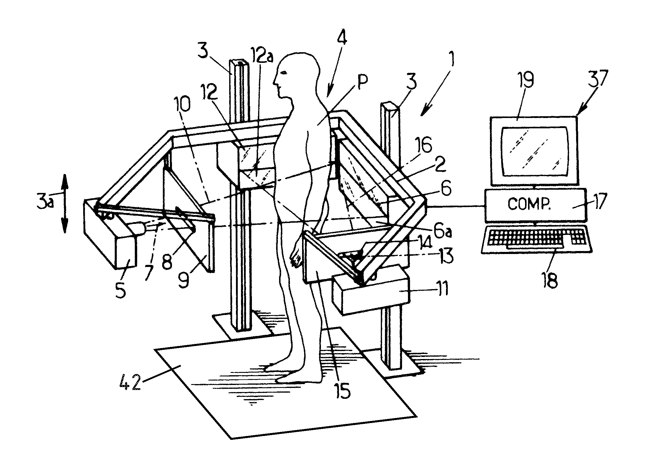
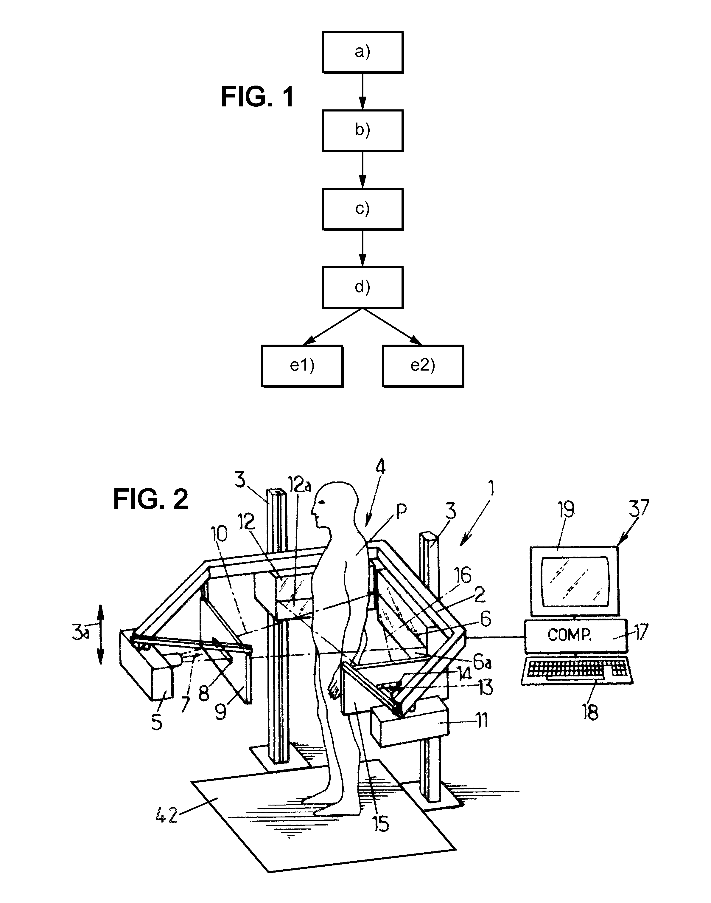
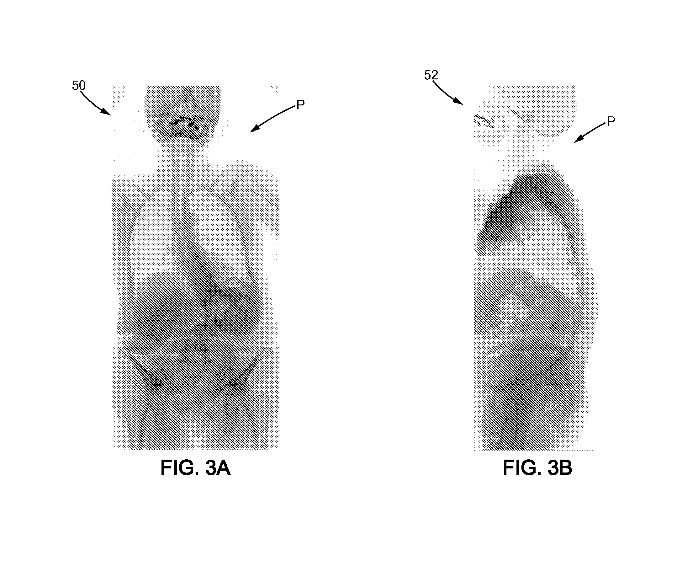
[0070]As illustrated on FIGS. 3A and 3B, during step a), two radiographic images 50 (frontal view), 52 (lateral view) of the spine 54 and of the pelvis 56 of patient P are taken by the apparatus 1.

[0071]Step b) and part of step c) are then performed automatically by the processor 17 to reconstruct the three-dimensional shape of the spine 54 and pelvis 56 of patient P (FIGS. 4A and 4B).

[0072]The reconstruction method used may be one of those described in document EP 1 168 249 B1. Naturally, other types of reconstruction methods may optionally be used in the context of the present invention. Such methods rely on placing in correspondence two representations of a given anatomical part on two calibrated X-ray radiographs.

[0073]Next, the practitioner manually identifies the part of the spine 54 on which the spinal implant 58 will be fixed, for example by clicking with th...

second embodiment

[0089]According to the invention, the method is a method for designing a hip implant for a patient needing hip replacement, for example due to arthritis pain or severe physical joint damage.

[0090]During step a), two radiographic images (frontal view and lateral view) of the femur of patient P are taken by the apparatus 1.

[0091]Step b) and part of step c) are then performed automatically by the processor 17 to reconstruct the three-dimensional shape of the upper portion of the femur 60 of patient P (FIG. 6).

[0092]The reconstruction method used may be the one described in document EP 1 168 249 B1. Naturally, other types of reconstruction methods may optionally be used in the context of the present invention.

[0093]At step c), three three-dimensional geometrical features of patient P are automatically determined by the processor 17.

[0094]These features are the femoral offset, the femoral neck angle and the internal surface of the femoral shaft 64.

[0095]In order to design a reliable and ...


PUM


Abstract

A method for designing a patient specific orthopaedic device intended for an osteoarticular structure of a patient, based on at least two two-dimensional radiographic images of the osteoarticular structure taken respectively in two offset image-taking directions, comprising the following steps: b) locating anatomical points on the radiographic images; c) determining at least one three-dimensional geometrical feature of the patient by matching the anatomical points b) located at step b); d) determining at least one three-dimensional size parameter of the orthopaedic device based on the geometrical feature of the patient determined at step c).

Description

FIELD OF THE INVENTION[0001]The instant invention relates to a method for designing a patient specific orthopaedic device from information obtained from a limited number of projected radiographs.BACKGROUND OF THE INVENTION[0002]Orthopaedic surgery relies upon anatomical pre-operative data obtained from imaging exams. In most cases, such exams are planar X-ray radiographs that allow to measure patient anatomical parameters and plan an adequate surgery.[0003]Such approaches can lead to the selection and positioning of a given implant, or to the planning of a given correction to spinal disorders from pre-operative data.[0004]Most recently, numerous techniques have been developed to derive patient specific devices from 3D information obtained from CT or MRI exams. These can be, in particular, patient specific surgical tools such as cutting guides or patient customized implants.[0005]However, these techniques are limited by their cost and by their inability to reflect the patient natural...

Claims


Application Information

Patent Timeline
Patent Type & Authority Applications(United States)
IPC IPC(8): G06F17/50
CPCA61B19/50A61B2034/102A61B2090/376A61B34/10A61B2034/108
Inventor GOMES, CHRISTOPHE
Owner EOS IMAGING
Why Eureka
Try Eureka