Apparatus and method for the position checking of a mechanical part

a technology for mechanical parts and apparatuses, applied in the direction of counting objects on conveyors, manufacturing tools, instruments, etc., can solve the problems of particularly expensive embodiments according to the former japanese patent application, and achieve the effects of accurate, reliable and inexpensive, and avoiding damag

Inactive Publication Date: 2007-07-24
MARPOSS SPA
View PDF5 Cites 0 Cited by
  • Summary
  • Abstract
  • Description
  • Claims
  • Application Information

AI Technical Summary

Benefits of technology

[0011]An object of the present invention is to provide an apparatus for detecting the presence of a mechanical part, and more specifically for checking the integrity of elongate tools, that can be utilized even in the case the positioning of the part to be checked is not extremely precise, that avoids causing damage to the former part and is accurate, reliable and inexpensive.
[0012]A further object of the invention is to provide an associated checking method with particular features of simplicity and safety.

Problems solved by technology

U.S. Pat. No. 3,912,925 are not suitable for checking tools arranged in the tool storage magazine, owing to the possible inclinations of the tools with respect to the axis due, as previously, to the inaccurate coupling between tool and associated seat.
The embodiment according to the former Japanese patent application is particularly expensive, especially in those cases when there is the need to simply check the integrity of the tool.

Method used


Image

  • Apparatus and method for the position checking of a mechanical part
  • Apparatus and method for the position checking of a mechanical part
  • Apparatus and method for the position checking of a mechanical part

Examples


Embodiment Construction

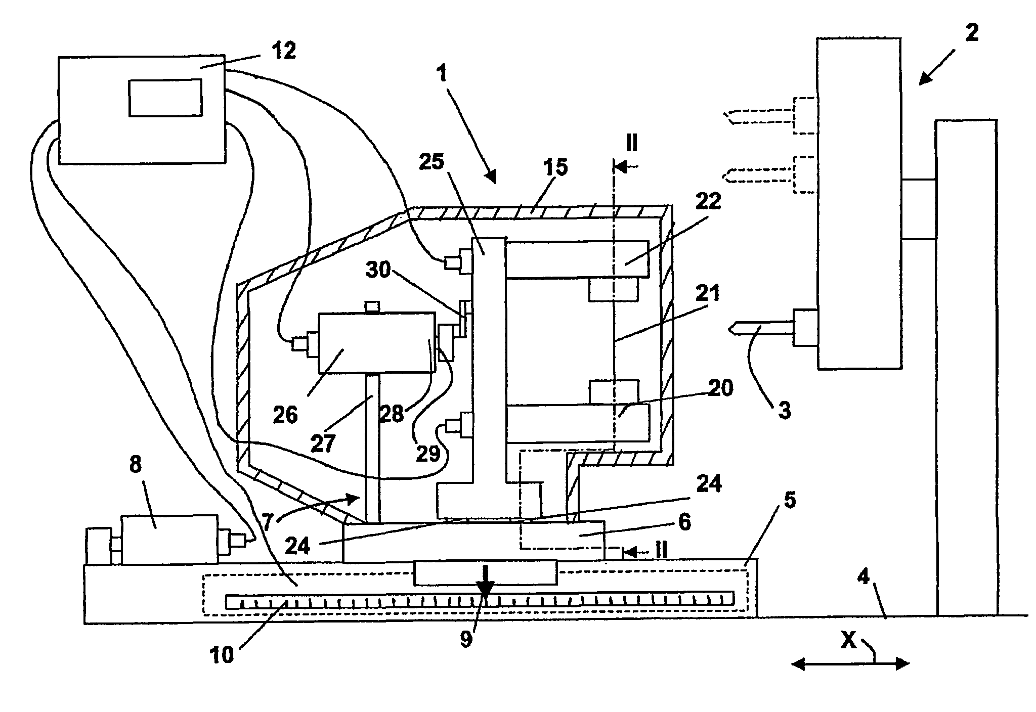
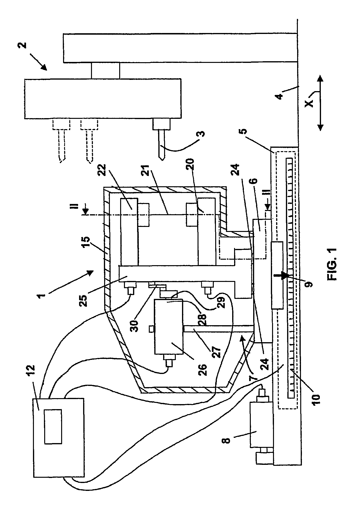
[0017]FIG. 1 illustrates a checking apparatus 1 represented in course of checking a mechanical part, in particular an elongate tool 3 coupled to a storage magazine 2 of a machine tool, for example a machining center, per se known and herein not illustrated.

[0018]A common bed 4 supports the storage magazine 2 and the apparatus 1. More specifically, a frame of the apparatus, shown in simplified form in FIG. 1 and identified by reference number 5, is rigidly coupled to bed 4 and carries a slide 6—movable with respect to frame 5 and consequently with respect to tool 3, along a longitudinal feed direction X—that forms a base for a hereinafter disclosed optoelectronic checking system 7.

[0019]A displacement system for controlling and checking the mutual position between base 6 and frame 5 includes, for example, a motor 8 that activates the displacements of the slide 6, with respect to the frame 5, and a position checking transducer device, for example a linear transducer. The linear transd...


PUM


Abstract

An apparatus for checking the integrity of tools includes an optoelectronic system (7) with a laser beam (21), a base (6) movable along a longitudinal direction (X) for enabling displacements between tool and optoelectronic system and a device for checking the mutual position including, for example, a transducer (9,10). A sensor (22) of the optoelectronic system detects the interruption of the beam and, on the basis of the transducer signal at said interruption and on the comparison with a known value, the integrity of the tool is determined. A coupling mechanism (24) of the optoelectronic system coupled at the base enables oscillations of the former along a transversal reference surface, that define a sensitive delimited area (33). The oscillations are controlled by means of a motor (26) and interruptions of the beam are detected and signalled by the sensor the moment that the end of the tool interferes with the sensitive delimited area.

Description

TECHNICAL FIELD[0001]The invention relates to an apparatus for checking the position of a mechanical part, more particularly a free end of an elongate tool, including a frame, stationary with respect to the mechanical part to be checked, a base carrying a mechanical support, the base and the frame being mutually movable along a longitudinal feed direction, an emitter for generating a light beam along a trajectory transversal with respect to the longitudinal feed direction, and a sensor, arranged along the trajectory of the light beam, the emitter and the sensor being coupled to the mechanical support in mutually defined positions, the sensor being adapted for providing signals indicative of the reception of the light beam, a transducer device for checking the mutual position between the base and the frame, and a processing, display and control unit, connected to the sensor and to the transducer device for processing the signals of the sensor and for identifying the mutual position b...

Claims


Application Information

Patent Timeline
Patent Type & Authority Patents(United States)
IPC IPC(8): H01J40/14B23Q17/22B23Q17/24
CPCB23Q17/22B23Q17/24Y02E60/324Y02E60/32
Inventor COZZARI, ALBERTODALL'AGLIO, CARLO
Owner MARPOSS SPA
Why Eureka
Try Eureka