Stent graft

a stent and graft technology, applied in the field of stent grafts, can solve the problems of stent graft displacement or twisted from its previously adopted optimal position, difficult compression, damage to the vessel wall, etc., and achieve the effect of less friction and easy releas

Active Publication Date: 2016-04-14
JOTEC
View PDF18 Cites 13 Cited by
  • Summary
  • Abstract
  • Description
  • Claims
  • Application Information

AI Technical Summary

Benefits of technology

[0010]Against this background, the object of the invention is to develop a stent graft of the type mentioned at the outset in such a way that the body can be compressed in a simple way and can likewise be easily released and expanded in a blood vessel with less friction.

Problems solved by technology

However, this has the disadvantage that the compression is made difficult since the person carrying out the treatment has to fold the body of the stent graft up in portions and at the same time insert it into the sleeve catheter until the latter fully encloses the body of the stent graft.
This may, on the one hand, cause damage to the vessel wall and, on the other hand, cause the stent graft to be displaced or twisted from its previously adopted optimal position.
The latter scenario necessitates awkward repositioning of the stent graft in the blood vessel.

Method used


Image

  • Stent graft
  • Stent graft
  • Stent graft

Examples


Embodiment Construction

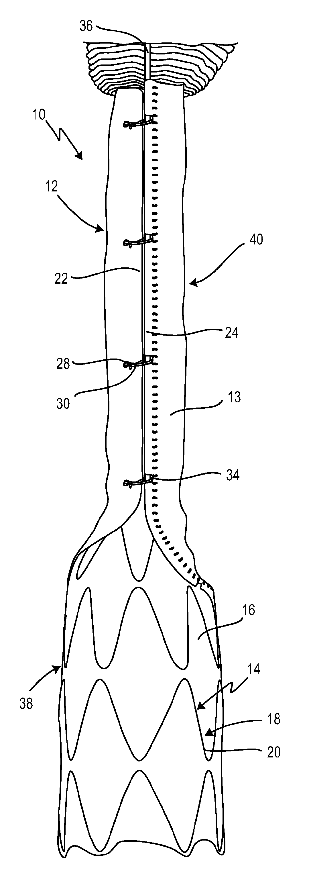
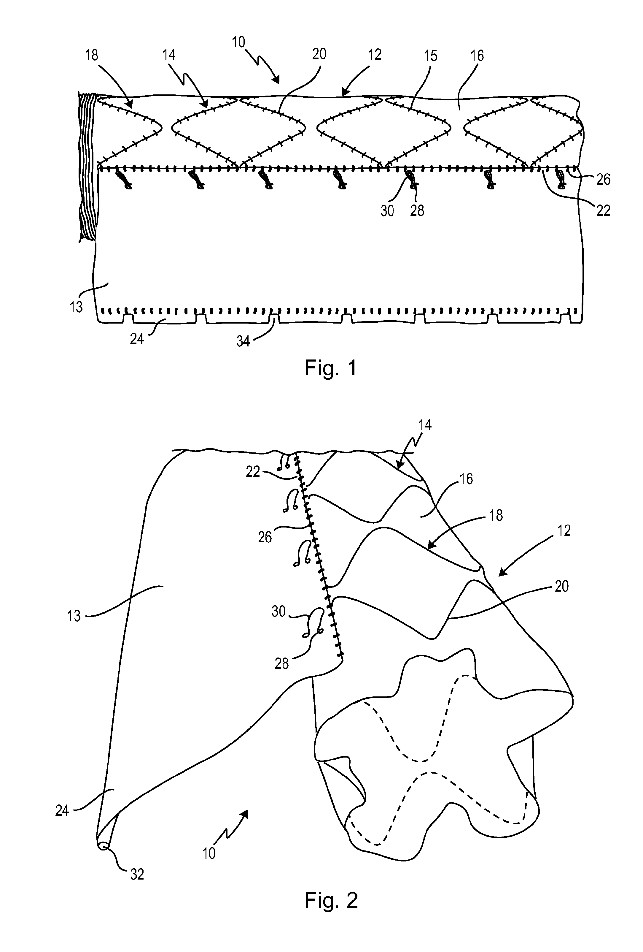
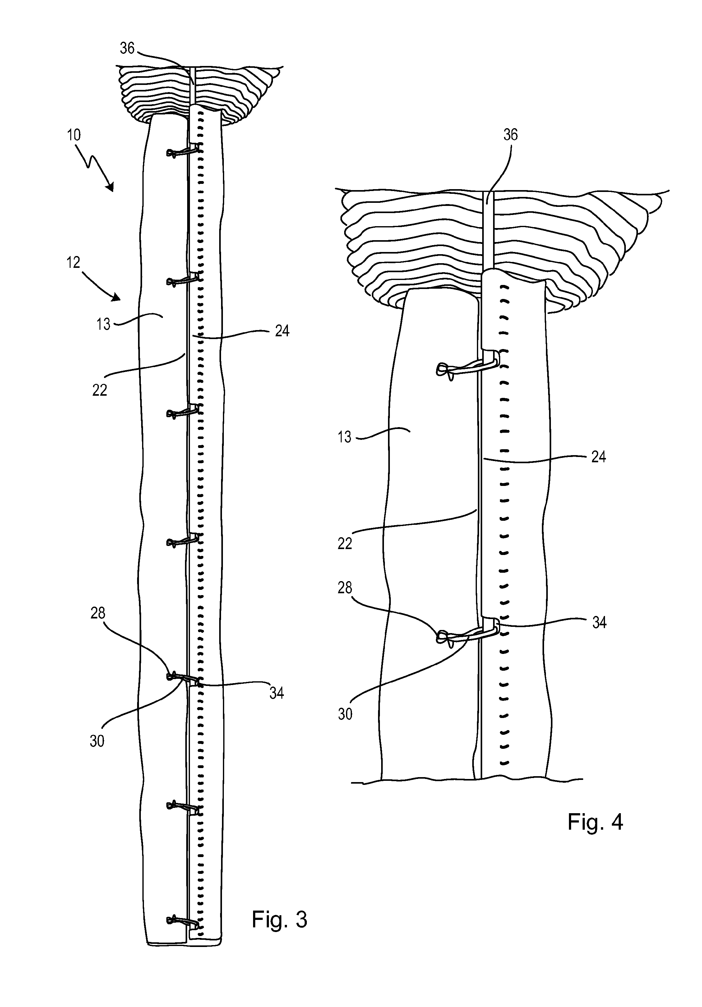
[0048]FIGS. 1 and 2 show an illustrative embodiment of a stent graft, designated generally by reference sign 10, which has a hollow cylindrical body 12 and a sleeve catheter, which is designed as a flap-shaped compression element 13. The body 12 has a self-expanding stent 14 and a prosthetic material 16. The stent 14 has ring segments 18 arranged in succession in the longitudinal direction of the hollow cylindrical body 12 and composed of meandering supports 20. The prosthetic material, for example a textile structure, is secured on the ring segments 18 by stitches 15, wherein the stitches are not shown in any of the subsequent figures.

[0049]As can be seen from the perspective view in FIG. 2, the body 12 is a hollow cylinder. The flap-shaped compression element 13 has a first longitudinal edge 22, secured on the body 12, and a free, second longitudinal edge 24, wherein the first longitudinal edge 22 is secured on the prosthetic material 16 by stitches 26. Perpendicularly with respec...


PUM


Abstract

A stent graft comprises a hollow cylindrical body and a sleeve catheter, wherein the body comprises at least a self-expanding stent and prosthetic material, wherein the body has a circumference in a compressed state which is smaller than a circumference of the body in an expanded state. The sleeve catheter is embodied as a flap-shaped compression element comprising two longitudinal edges, wherein a first longitudinal edge is attached to the body, wherein an extent of the flap-shaped compression element perpendicular to the first longitudinal edge is smaller than the circumference of the body in the expanded state, wherein, for compressing the body, the flap-shaped compression element can be placed around the body and a free second longitudinal edge is detachably fixable to fixation points arranged on the body and/or on the flap-shaped compression element.

Description

CROSS-REFERENCES TO RELATED APPLICATIONS[0001]This application is a continuation of international patent application PCT / EP2014 / 062784, filed on Jun. 18, 2014, designating the U.S., which international patent application has been published in German language and claims priority from German patent application DE 10 2013 106 463.9. filed on Jun. 20, 2013. The entire contents of these priority applications are incorporated herein by reference.BACKGROUND OF THE INVENTION[0002]The present invention relates to a stent graft with a hollow cylindrical body and a sleeve catheter, wherein the body has at least one self-expanding stent and a prosthetic material, wherein the body, in a compressed state, has a circumference that is smaller than a circumference of the body in an expanded state.[0003]Stent grafts of this kind are well known in the prior art. These are in the form of a medical implant which is inserted into hollow organs, for example blood vessels, of a patient in order to keep ope...

Claims


Application Information

Patent Timeline
Patent Type & Authority Applications(United States)
IPC IPC(8): A61F2/97A61F2/844A61F2/89A61F2/07
CPCA61F2/97A61F2/07A61F2002/9511A61F2/89A61F2/844
Inventor LESMEISTER, RAINERBARTHOLD, FRANZ-PETER
Owner JOTEC
Why Eureka
Try Eureka