Lock with a door handle contact

a technology of door handle and lock, applied in the field of locks, can solve the problems of inability to retrofit known locks, material fatigue of microswitch, loss of good functioning of microswitch, etc., and achieve the effect of simplifying the adjustment of the switching order and being flexible in its application

Inactive Publication Date: 2016-04-14
DORMAKABA DEUT GMBH
View PDF2 Cites 1 Cited by
  • Summary
  • Abstract
  • Description
  • Claims
  • Application Information

AI Technical Summary

Benefits of technology

[0006]The invention seeks to overcome the known disadvantages of the state-of-the-art. Particularly, the invention provides a lock with a door handle contact, which is versat

Problems solved by technology

The known locks are disadvantageous in that they are specified with regard to their orientation, i. e. the side of the escape direction and the side of the access authorization, because the positioning of the door handle contact, which is configured as a microswitch, is determined when the microswitch is bonded.
Therefore, subsequent retrofitting of the known locks is not possible.
In addition, the known locks are disadvantageous in that, when the switch tag of the microswitch, which is c

Method used


Image

  • Lock with a door handle contact
  • Lock with a door handle contact
  • Lock with a door handle contact

Examples


Embodiment Construction

[0019]Throughout the different Figures, the same parts are always identified by the same reference numeral, and therefore they will be normally only described once.

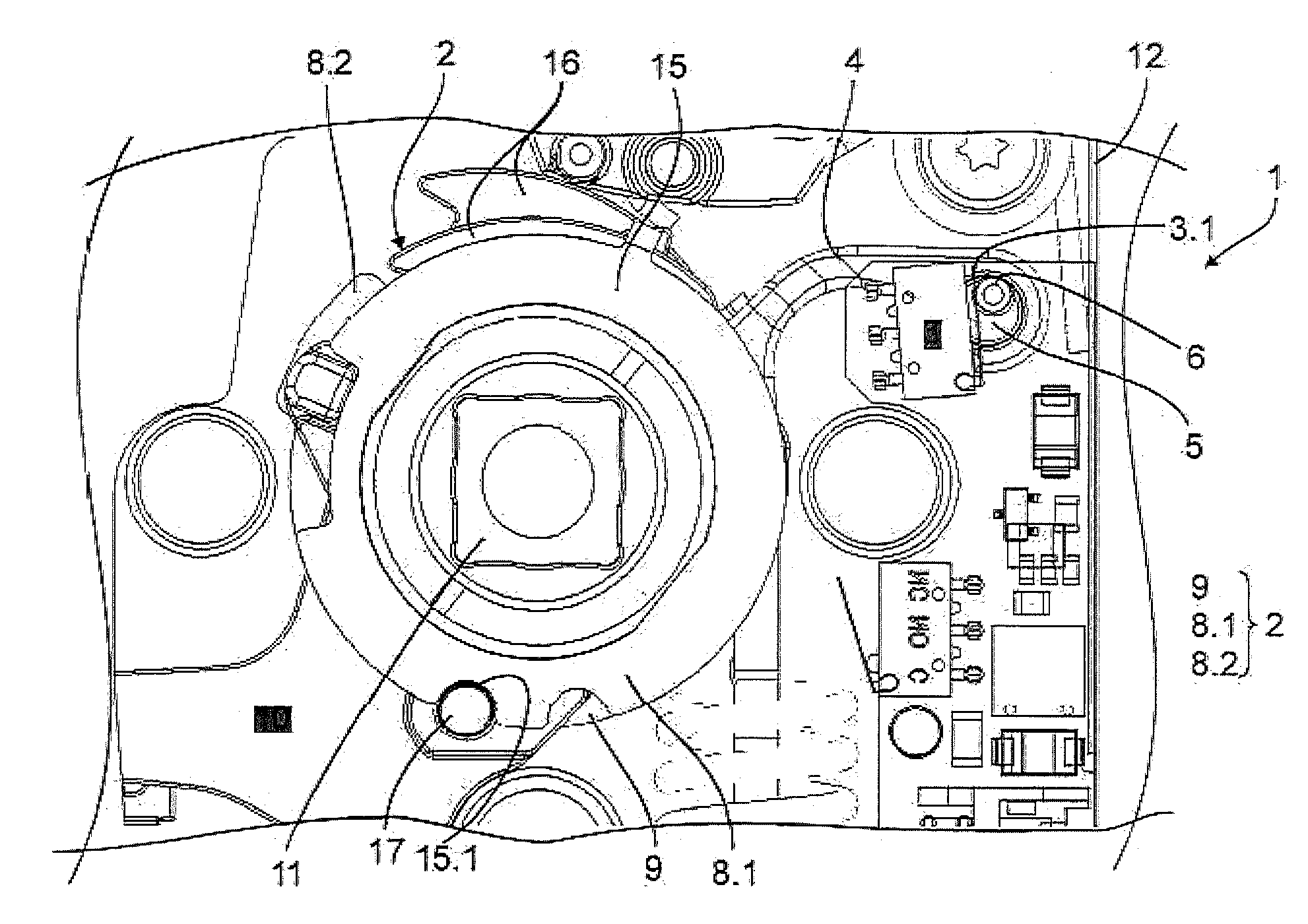
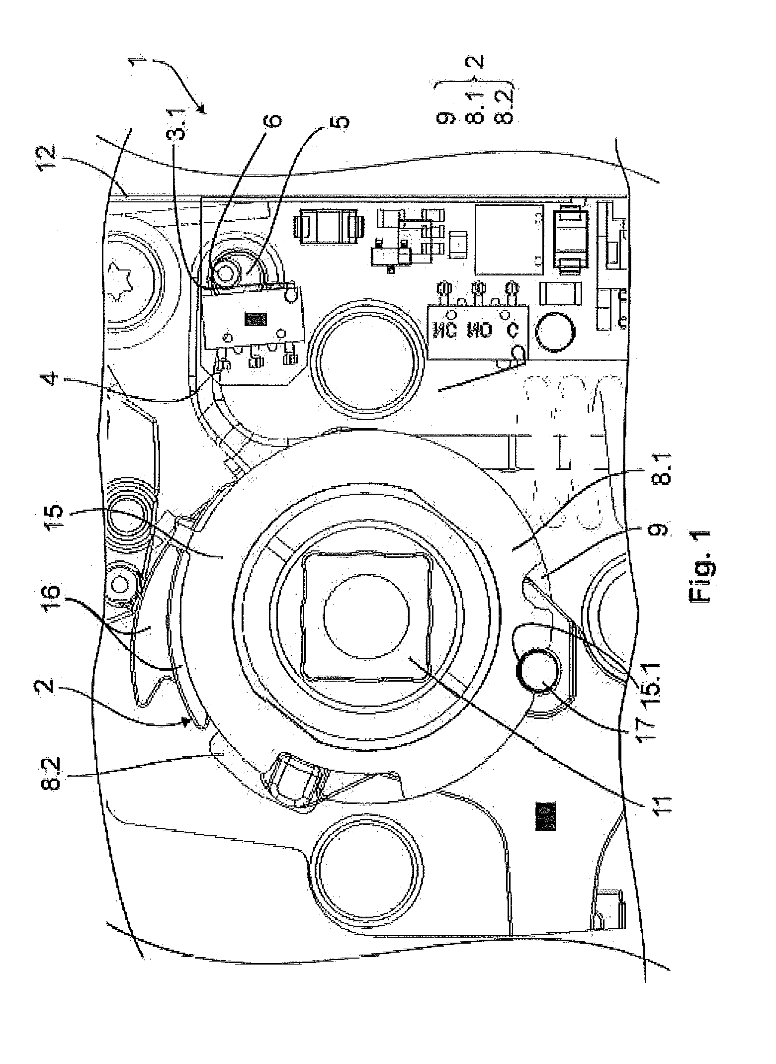
[0020]FIG. 1 shows a section of an inventive lock 1, wherein preferably the functional elements of the lock 1 relevant for the invention are identified. However, the limitation to the functional elements, respectively features of the lock relevant to the invention is not intended to be delimiting to the functioning of the lock 1. All functional elements of the lock 1 are disposed in a lock casing 12, which can be inserted into a door.

[0021]The lock 1 includes a follower 2, which can be coupled and uncoupled, and is operatively connected to a door handle which is not illustrated here via a handle reception 11. In the present case, the follower 2 comprises a front follower-half 8.1 and a rear follower-half 8.2, and a follower center member 9. Following a positive authorization or a granted access request directed to an acce...


PUM


Abstract

A lock with a door handle and/or an anti-panic bar, which is/are operatively connected to a follower that can be coupled and uncoupled, with an electromechanical energizing unit and at least one sensor for the access control of a door, where in an uncoupled condition of the follower, the follower is in a contact position with the sensor, and wherein by activating the electromechanical energizing unit, the follower can be transferred into a coupling condition, wherein, in the coupling condition, the follower releases the sensor into a release position by actuating the door handle and/or the anti-panic bar, where the follower includes an arm with a rotatably supported actuating element, where, in the coupling condition, by actuating the door handle and/or the anti-panic bar, the actuating element releases the sensor from the contact position into the release position.

Description

CROSS REFERENCE TO RELATED APPLICATION[0001]This application is related to and claims the benefit of German Patent Application Number 102014220412 filed on 8 Oct. 2014, the contents of which are herein incorporated by reference in their entirety.TECHNICAL FIELD[0002]The present invention relates to a lock as well as to an access control method for a door including a lock.BACKGROUND[0003]Locks defining said species are mostly equipped with a dead-bolt and a latch-bolt, which together with other mechanical and electronical functional elements of the lock are disposed in a lock casing. Usually, the latch-bolt and the dead-bolt can be unlocked together by means of an inside door handle, which is located within the building and inside the follower or the handle follower, for example of an anti-panic lock. On the outside of the door, i. e. outside the building or an area accessible only with an access authorization, without prior access authorization via the outside door handle, the dead-...

Claims


Application Information

Patent Timeline
IPC IPC(8): E05B63/00E05B47/00H02K7/14E05F15/70E05F15/40E05B65/10E05F15/603
CPCE05B47/0012E05F15/603E05F15/70E05F15/40E05B65/1046E05B2047/0048E05B2047/0084E05B2047/0067E05B63/0069H02K7/14E05B17/22E05B47/0676
Inventor SCHNEIDER, MARC-ANDREGRONE, KAI
Owner DORMAKABA DEUT GMBH
Why Eureka
Try Eureka