System and method for retaining wall

a technology of retaining walls and systems, applied in excavations, artificial islands, construction, etc., can solve the problems of affecting the safety of construction workers, and failing to provide methods and systems for fast and secure connection of tiebacks to wall panels, etc., to achieve universal function, simple fabrication, and versatile in application and operation.

Active Publication Date: 2015-03-05
OLDCASTLE PRECAST
View PDF11 Cites 8 Cited by
  • Summary
  • Abstract
  • Description
  • Claims
  • Application Information

AI Technical Summary

Benefits of technology

[0005]In view of the limitations now present in the prior art systems and methods for mechanically stabilized earthen retaining walls, the present invention provides a new and useful mechanically stabilized earth retaining wall block system and method of use thereof which is simpler in fabrication, more universally functional and more versatile in application and operation than known prior art methods or devices.

Problems solved by technology

For example, known devices and systems fail to provide methods and systems for fast and secure connection of tiebacks to a wall panel while reducing risk of damaging or spalling or damaging the panel.

Method used


Image

  • System and method for retaining wall
  • System and method for retaining wall
  • System and method for retaining wall

Examples


Embodiment Construction

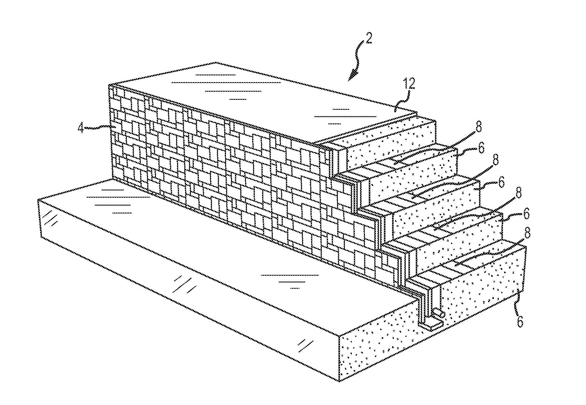
[0037]Referring now to FIG. 1, a retaining wall system according to one embodiment of the present invention is provided. As shown, a retaining wall 2 is provided and comprises a plurality of blocks 4. The retaining wall 2 of FIG. 1 is provided as a substantially vertical planar element for containing a fill material 6. The term “fill” as used herein refers to a broad array of fill contents to be contained or restrained by a wall. Fill 6 includes, but is not limited to earthen materials, rock, sand, natural and artificial materials, and various combinations thereof. Accordingly, no limitation with respect to types of fill 6 is provided herein.

[0038]As shown in FIG. 1, a retaining wall 2 comprising a plurality of blocks 4 is adapted to retain a fill material 6, which may further comprise a cover layer 12 such as grass, turf, artificial turf, carpet, etc. One or more tieback members 8 are provided as generally extending from rows of blocks 4, the rows of blocks 4 extending in a horizon...


PUM


Abstract

A retaining wall system for mechanically stabilizing an earthen wall is provided. The system comprises a plurality of modular block members that may be assembled in a number of desired states or orientations. Tieback members for supporting the wall and related fill are provided and the wall comprises interconnection members for the tieback members.

Description

[0001]This U.S. Non-Provisional Patent Application claims priority to U.S. Provisional Patent Application Ser. No. 61 / 871,133, filed Aug. 28, 2013, the entire disclosure of which is hereby incorporated by reference in its entirety.FIELD OF THE INVENTION[0002]The present invention relates generally to retaining wall systems. More specifically, the present invention relates to a unique mechanically stabilized earth retaining wall block system and method of use thereof.BACKGROUND[0003]Known retaining wall structures, including those disclosed in U.S. Pat. No. 4,824,293 to Brown et al., which is hereby incorporated by reference in its entirety, fail to disclose various features of the present invention. Brown et al. provide an elongated slit on one side of a panel, but fail to disclose various features of the present invention as shown and described herein, including members, anchor members, and attachment means of the present invention.[0004]U.S. Pat. No. 4,668,129 to Babcock et al., U...

Claims


Application Information

Patent Timeline
Patent Type & Authority Applications(United States)
IPC IPC(8): E02D29/02
CPCE02D29/0266E02D29/02
Inventor BROOKHART, CLINTONUSAGANI, ROBINSON
Owner OLDCASTLE PRECAST
Why Eureka
Try Eureka