Fuel piping arrangement in common rail type fuel supply systems

a fuel supply system and common rail technology, applied in the direction of liquid fuel feeders low-pressure fuel injection, etc., can solve problems such as leakage and pipe breakage, and achieve the effect of increasing the safety against leakage into engine oil

Active Publication Date: 2016-04-14
FPT MOTORENFORSCHUNG
View PDF21 Cites 4 Cited by
  • Summary
  • Abstract
  • Description
  • Claims
  • Application Information

AI Technical Summary

Benefits of technology

[0009]Therefore it is the main object of the present invention to provide a fuel piping arrangement in common rail type...

Problems solved by technology

Any inaccuracy of the production of such components, and also the differences among the branch pipes, could i...

Method used


Image

  • Fuel piping arrangement in common rail type fuel supply systems
  • Fuel piping arrangement in common rail type fuel supply systems
  • Fuel piping arrangement in common rail type fuel supply systems

Examples


Embodiment Construction

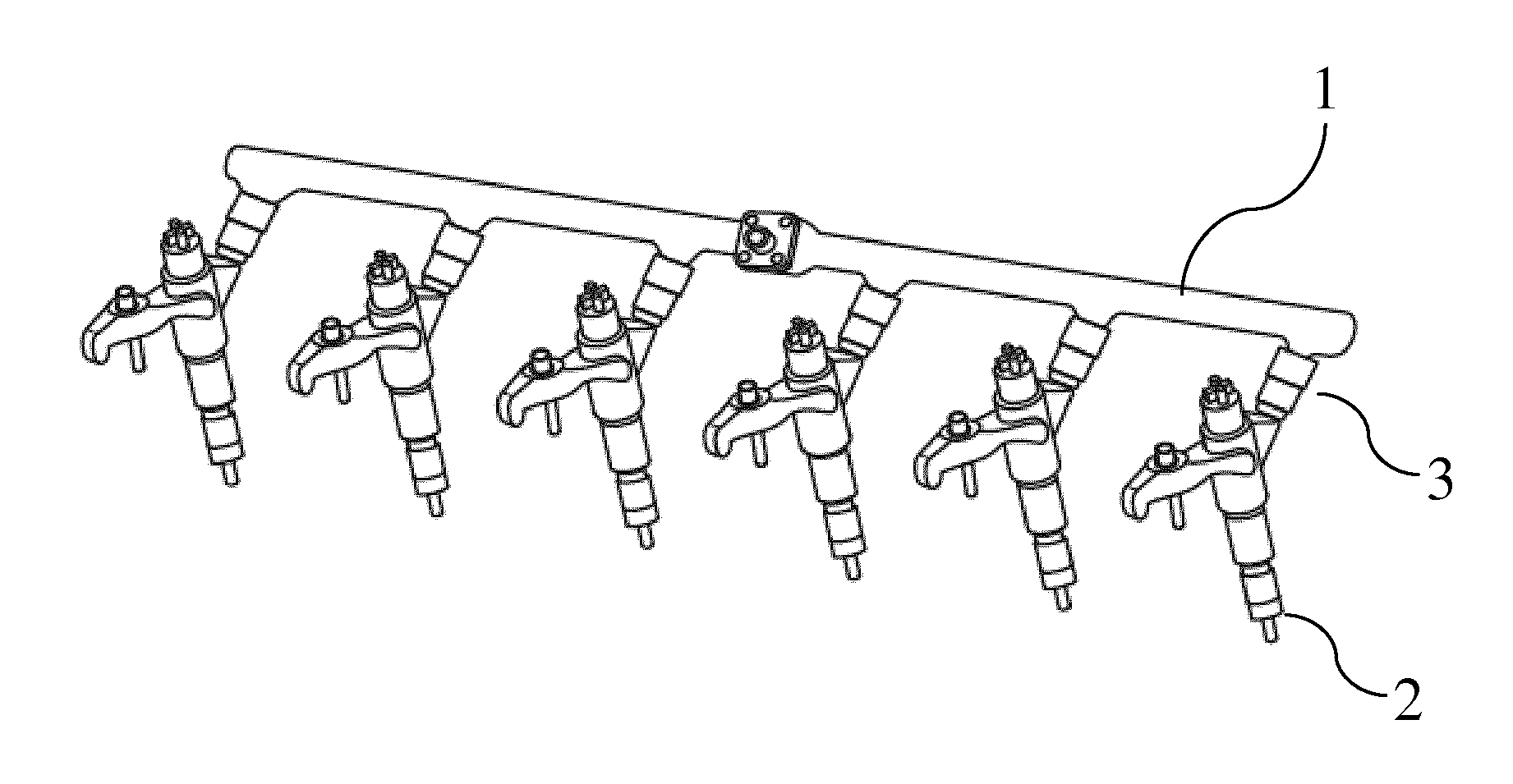
[0020]According to the present invention, the common rail 1 is directly connected with the input port 3 of the injector 2.

[0021]The common rail 1 runs horizontally, parallel with an engine bank B.

[0022]The type of joint for connecting the common rail 11 with the injector input port 21 can be any. The absence of any kind of branch pipe means that only one joint is present between the common rail and the injector, by bringing the respective ports joined together.

[0023]FIG. 1 shows six injectors aligned along a direction, with the common rail directly connected with the injectors.

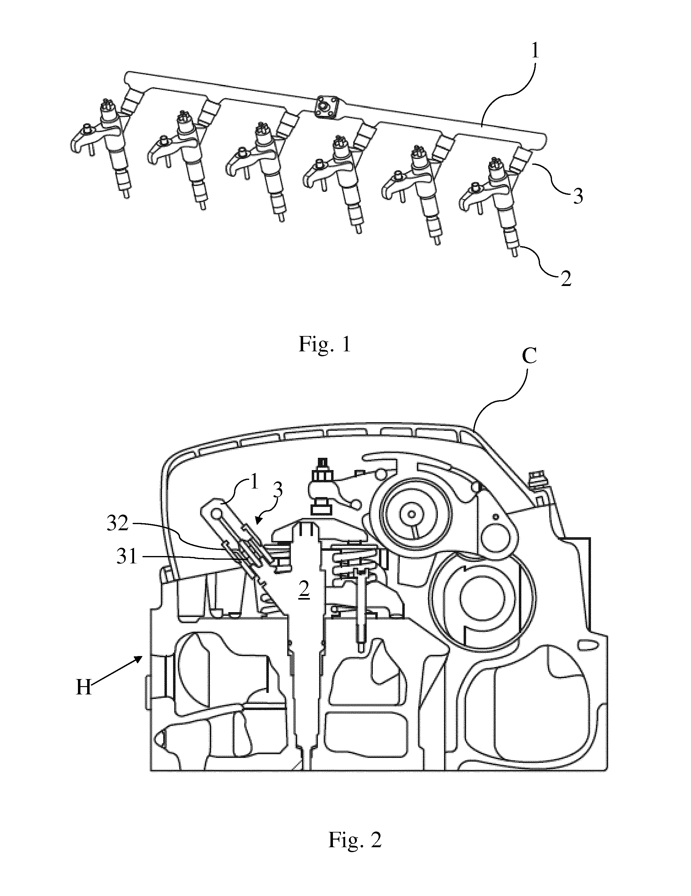
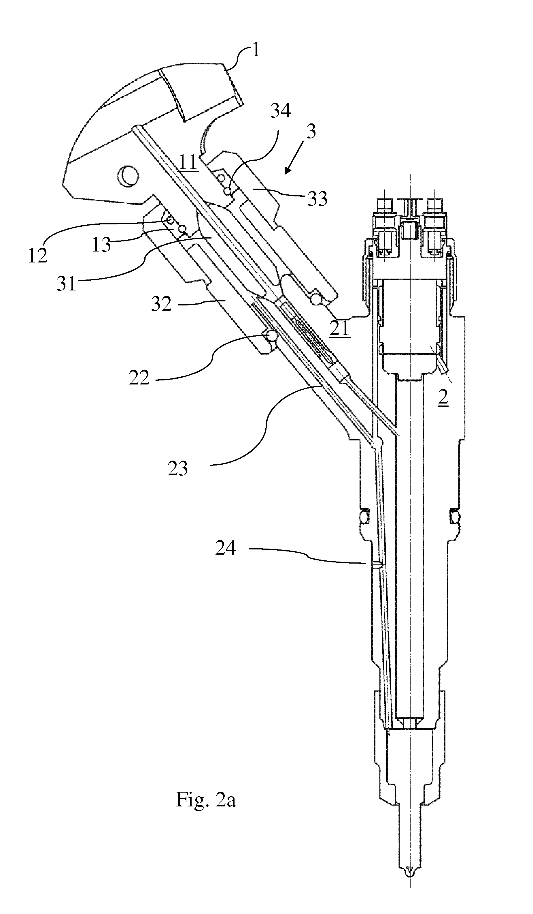
[0024]FIGS. 2 and 2a, show a cross-sectional view of an engine head, drawn perpendicularly with respect to the common rail alignment and passing through one of the several injectors 2. Therefore, the cross-sectional view is longitudinal with respect to the injector development.

[0025]Having, usually, either the common rail port or the input port 21 of the injector a concave shape, an adapting element 31 can be ...


PUM


Abstract

The present invention provides for a fuel piping arrangement in common rail type fuel supply systems, the supply system comprising at least one common rail and at least one respective injector, wherein the common rail is connected with the at least one injector directly, by means of only one joint.

Description

CROSS REFERENCE TO RELATED APPLICATIONS[0001]The present application claims priority to PCT International Application No. PCT / EP2014 / 062208 filed on Jun. 12, 2014, which application claims priority to European Patent Application No. 13172010.4 filed Jun. 14, 2013, the entirety of the disclosures of which are expressly incorporated herein by reference.STATEMENT RE: FEDERALLY SPONSORED RESEARCH / DEVELOPMENT[0002]Not Applicable.FIELD OF THE INVENTION[0003]The present invention relates to a fuel piping arrangement in common rail type fuel supply systems, in particular in the field of heavy vehicles.DESCRIPTION OF THE PRIOR ART[0004]The fuel supply systems of the common rail type usually comprise a single common pipe for each cylinder bank that supplies the middle or high pressurized fuel.[0005]Such common pipe is disposed horizontally, parallel with the cylinder bank outside the head cover of the engine and, for each injector, a branch pipe connects such injector with the common pipe / rai...

Claims


Application Information

Patent Timeline
IPC IPC(8): F02M55/02
CPCF02M55/025F02M39/00F02M55/005F02M2200/856
Inventor HARTER, MICHAEL
Owner FPT MOTORENFORSCHUNG
Why Eureka
Try Eureka