

Coupling and a method of using the same
a technology of coupling and fluid, applied in the direction of gearing details, mechanical equipment, machines/engines, etc., can solve the problems the effect of affecting the flow rate of the fluid, and the leakage of the seal, so as to achieve convenient use for users
- Summary
- Abstract
- Description
- Claims
- Application Information
AI Technical Summary
Benefits of technology
Problems solved by technology
Method used
Image

Examples
first embodiment
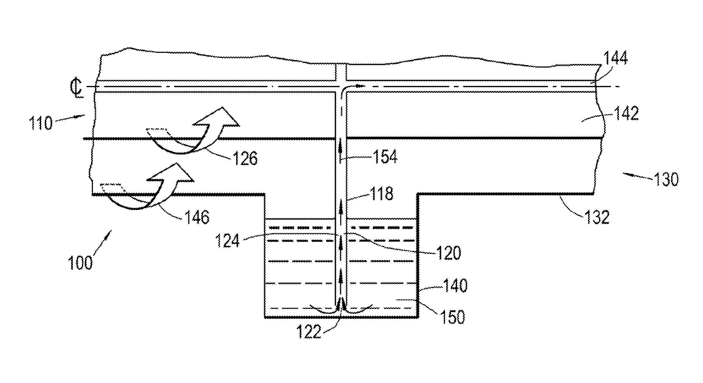
[0061]Referring to FIGS. 1 and 2A, a fluid transfer coupling according to the invention is designated generally by the reference numeral 100. The fluid transfer coupling 100 comprises a first shaft assembly 110 and a second shaft assembly 130. In the embodiment shown, the fluid transfer coupling forms part of an epicyclic gearbox (not shown) within a gas turbine engine (not shown).
[0062]Speed ratios will be an output of the wider engine architecture—the trough will rotate with the power gearbox input (or sun) gear, while the fin will rotate with the output (planet carrier).
[0063]Each of the first shaft assembly 110 and the second shaft assembly 130 is formed from a alloy steel suitable for use in an epicyclic gearbox.
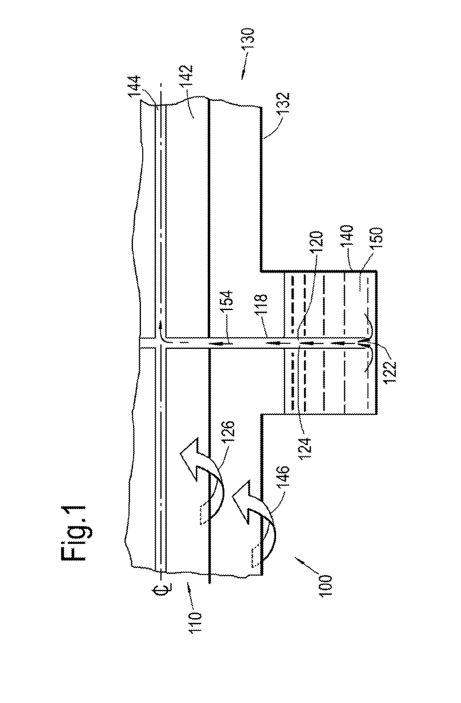
[0064]The first shaft assembly 110 comprises a first shaft 112, and an annular fin 118 attached to the first shaft 112. The first shaft has a centre portion 114. In the present embodiment the centre portion 114 is a hole extending axially along the centre line of the fi...
second embodiment
[0074]FIG. 2B shows a first shaft assembly 210 of a fluid transfer coupling 200 according to the invention. Features of the first shaft assembly 210 which correspond to those of first shaft assembly 110 have been given corresponding reference numerals for ease of reference.
[0075]In the first shaft assembly 210 of this arrangement comprises a first shaft 112 and an annular fin 218. The annular fin 218 is attached to the first shaft 112.
[0076]The annular fin 218 comprises one or more internal passages 220. In this arrangement, the one or more internal passages 220 are formed as a plurality of holes 224, each of the holes 224 extending radially outwardly from the centre portion 114 of the first shaft 112 to a radially outwardly facing side 222 of the annular fin 218.
[0077]In use the fluid transfer coupling 200 operates in the same manner as outlined above in respect of the fluid transfer coupling 100.
third embodiment
[0078]FIG. 3 shows a first shaft assembly 310 of a fluid transfer coupling 300 (not shown) according to the invention. Features of the first shaft assembly 310 which correspond to those of first shaft assembly 110 have been given corresponding reference numerals for ease of reference.
[0079]In this arrangement, the first shaft assembly 310 comprises a first shaft 112 and an annular fin 318 attached to the first shaft 112. As outlined above for the previous embodiments, the annular fin 318 comprises one or more internal passages 320 in the form of a single annular volume 324.
[0080]The annular volume 324 fluidly connects the centre portion 114 of the first shaft 112 to a radially outwardly facing side 322 of the annular fin 318.
[0081]In this arrangement, the annular volume 324 is provided with a plurality of radially extending first vanes 326. These vanes 326 serve to minimise the circumferential velocity of fluid contained within and being driven through the annular volume 324.
[0082]I...
PUM
 Abstract
Description
Claims
Application Information