Fast reboot for a switch

a switch and fast technology, applied in the field of communication networks, can solve the problems of high cost, limited physical space, power consumption, design complexity, etc., and achieve the effect of increasing the complexity of the switch, increasing the cost of the switch, and increasing the size of the switch

Active Publication Date: 2016-04-14
AVAGO TECH INT SALES PTE LTD
View PDF7 Cites 110 Cited by
  • Summary
  • Abstract
  • Description
  • Claims
  • Application Information

AI Technical Summary

Benefits of technology

[0009]One embodiment of the present invention provides a switch. The switch includes a packet processor, a persistent storage module, and a boot-up management module. The packet processor identifies a switch identifier associated with the switch in the header of a packet. The persistent storage module stores configuration information of the switch in a first table in a local persistent storage. This configuration information is included in a configuration file, and the first table includes one or more columns for the attribute values of the configuration information. The boot-up management module loads the attribute values to corresponding switch modules from the first table without processing the configuration file.

Problems solved by technology

However, the size of a switch cannot grow infinitely.
It is limited by physical space, power consumption, and design complexity, to name a few factors.
Furthermore, switches with higher capability are usually more complex and expensive.
More importantly, because an overly large and complex system often does not provide economy of scale, simply increasing the size and capability of a switch may prove economically unviable due to the increased per-port cost.
Managing persistent storage in unstructured format is inefficient and requires runtime structuring.
While persistent storage brings many desirable features to a switch, some issues remain unsolved in efficiently facilitating persistent storage in a structured way in a switch.

Method used


Image

  • Fast reboot for a switch
  • Fast reboot for a switch
  • Fast reboot for a switch

Examples


Embodiment Construction

[0040]The following description is presented to enable any person skilled in the art to make and use the invention, and is provided in the context of a particular application and its requirements. Various modifications to the disclosed embodiments will be readily apparent to those skilled in the art, and the general principles defined herein may be applied to other embodiments and applications without departing from the spirit and scope of the present invention. Thus, the present invention is not limited to the embodiments shown, but is to be accorded the widest scope consistent with the claims.

Overview

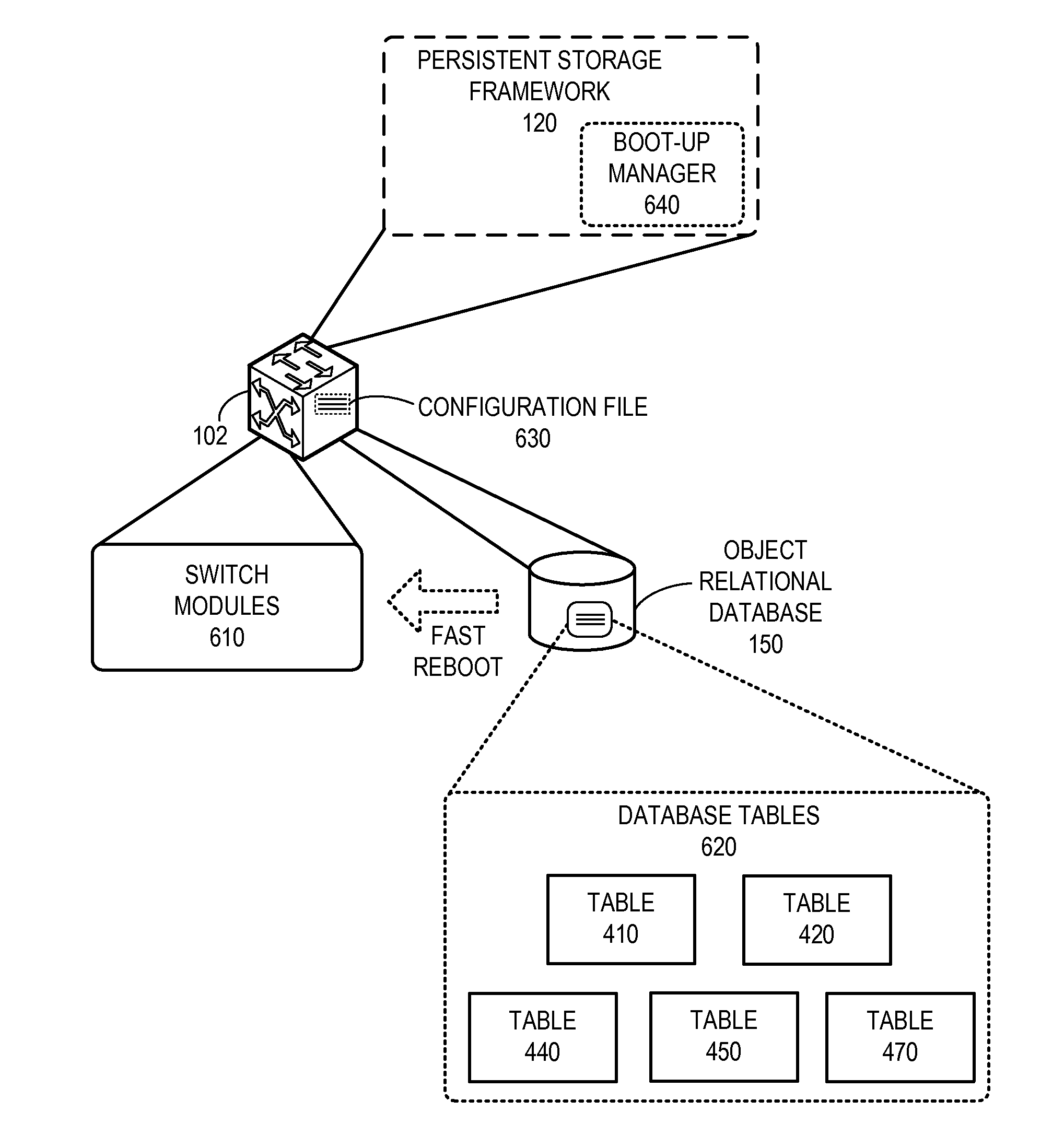
[0041]In embodiments of the present invention, the problem of efficiently rebooting a switch is solved by storing configuration information of the switch in a persistent storage, such as an object relational database. During reboot, the configuration information is loaded into the switch modules (e.g., processing hardware of the switch, such as an application-specific integrated circu...


PUM


Abstract

One embodiment of the present invention provides a switch. The switch includes a packet processor, a persistent storage module, and a boot-up management module. The packet processor identifies a switch identifier associated with the switch in the header of a packet. The persistent storage module stores configuration information of the switch in a first table in a local persistent storage. This configuration information is included in a configuration file, and the first table includes one or more columns for the attribute values of the configuration information. The boot-up management module loads the attribute values to corresponding switch modules from the first table without processing the configuration file.

Description

RELATED APPLICATION[0001]The present disclosure is related to U.S. patent application Ser. No. 13 / 087,239, Attorney Docket Number BRCD-3008.1.US.NP, titled “Virtual Cluster Switching,” by inventors Suresh Vobbilisetty and Dilip Chatwani, filed 14 Apr. 2011, the disclosure of which is incorporated by reference herein.BACKGROUND[0002]1. Field[0003]The present disclosure relates to communication networks. More specifically, the present disclosure relates to a method for a constructing a scalable system that facilitates persistent storage in a switch.[0004]2. Related Art[0005]The exponential growth of the Internet has made it a popular delivery medium for a variety of applications running on physical and virtual devices. Such applications have brought with them an increasing demand for bandwidth. As a result, equipment vendors race to build larger and faster switches with versatile capabilities. However, the size of a switch cannot grow infinitely. It is limited by physical space, power...

Claims


Application Information

Patent Timeline
Patent Type & Authority Applications(United States)
IPC IPC(8): G06F9/445H04L12/741G06F9/44H04L12/24H04L45/74
CPCG06F9/44505H04L41/0853G06F9/4401H04L45/74H04L41/0856G06F8/35H04L41/046H04L41/0806H04L41/0869H04L41/0233
Inventor GUNTAKA, VIDYASAGARA R.VOBBILISETTY, SURESHGOWDA, MANJUNATH A.G.DURAISWAMY, PASUPATHI
Owner AVAGO TECH INT SALES PTE LTD
Why Eureka
Try Eureka