
Connector

a technology of connecting pins and connectors, applied in the direction of coupling device connections, electrical discharge lamps, coupling device details, etc., can solve the problems of increasing the size of the connector, and affecting the reliability of connection detection

Active Publication Date: 2016-04-14
SUMITOMO WIRING SYST LTD
View PDF8 Cites 3 Cited by
  • Summary
  • Abstract
  • Description
  • Claims
  • Application Information

AI Technical Summary

Benefits of technology

This patent is about a device that helps connect two electronic devices. It includes a resilient stopper that is designed to move and absorb shocks during connection. The device has a first support point and a second support point to provide stability and prevent damage to the device. The device also has a lock that can be connected to a lock on the other device. The lock arm is designed to bend and make contact with the lock, providing a reliable connection. The device is stable and easy to use, and helps to improve the overall performance of the electronic devices.

Problems solved by technology

In the case of the above conventional connector, if locking between the resilient stopper and the stopper receiving portion should be accidentally released in the process of connecting the first and second housings, the slider is moved to the retracted position by the spring force of the coil spring, causing a problem of impairing the reliability of connection detection.
If a reaction force of the resilient stopper is increased in view of this, it becomes difficult to release locking between the resilient stopper and the stopper receiving portion.
However, if a shear area of the entire resilient stopper is increased to increase the reaction force of the resilient stopper, the resilient stopper is enlarged, consequently increasing the size of the connector.
Since the lock arm is deflected and deformed in the process of connecting the first and second housings, the protrusion is unlikely to contact the lock arm in motion and it is difficult to form the second supporting point portion.

Method used


Image

  • Connector
  • Connector
  • Connector

Examples


Embodiment Construction

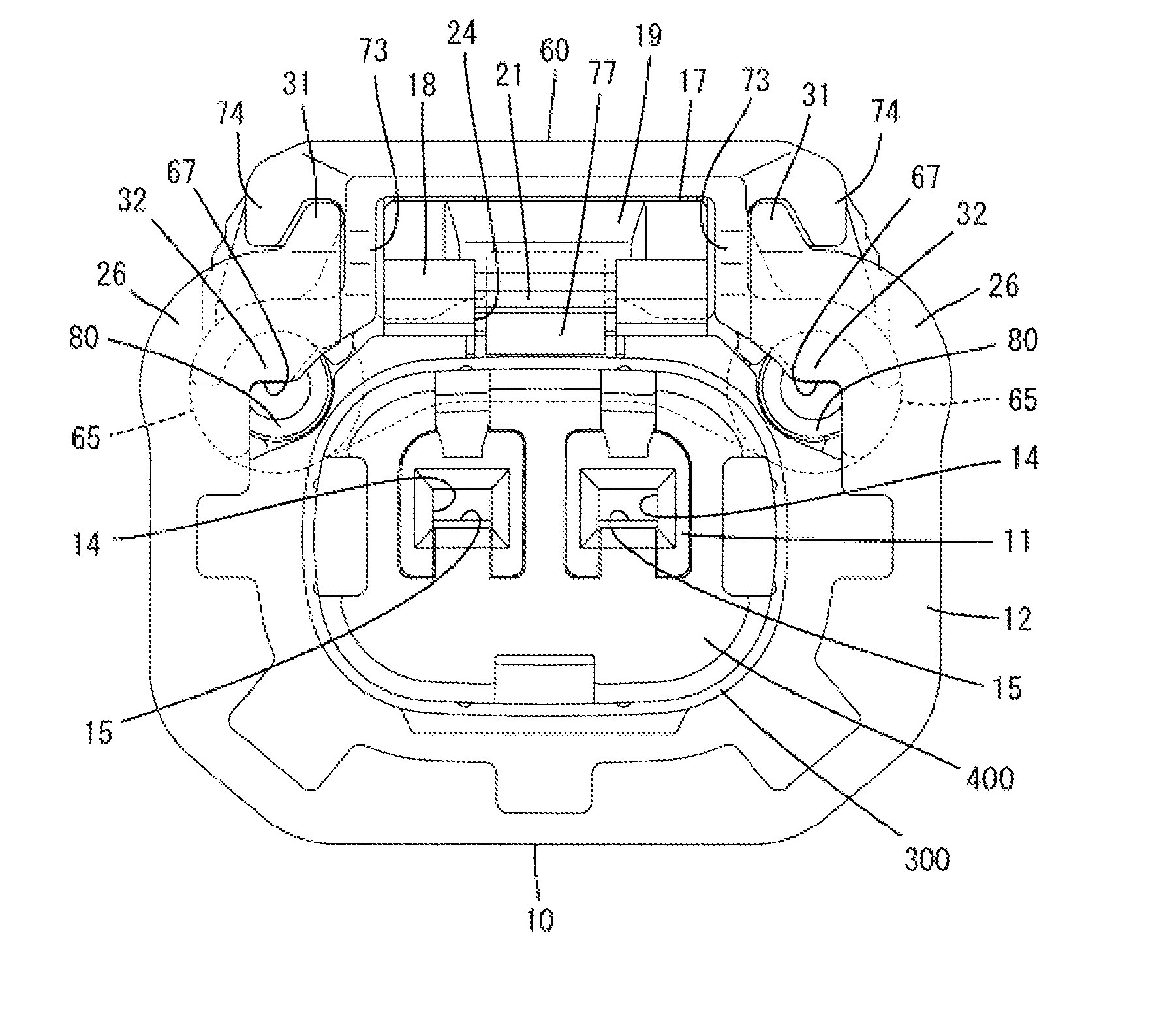
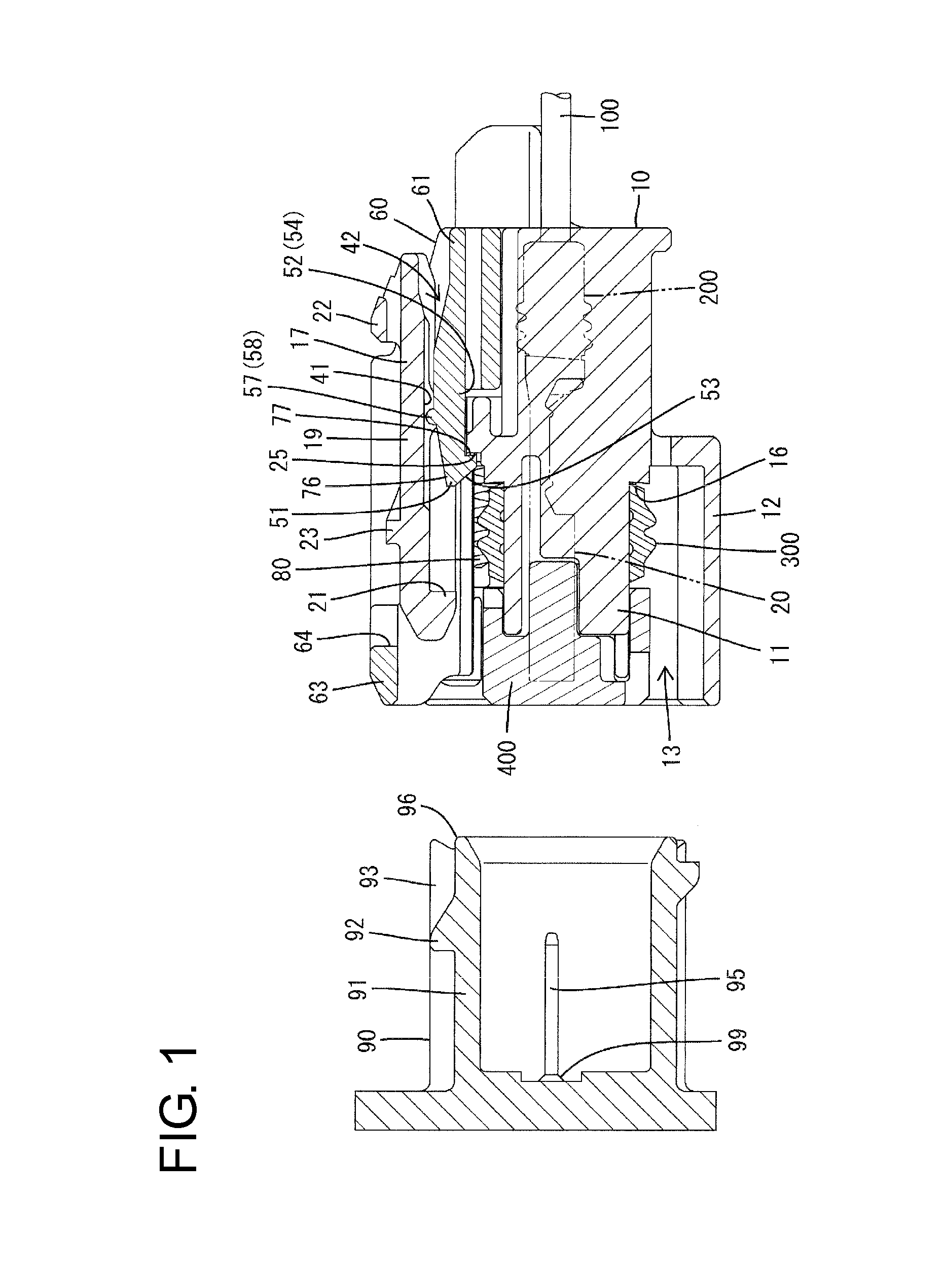
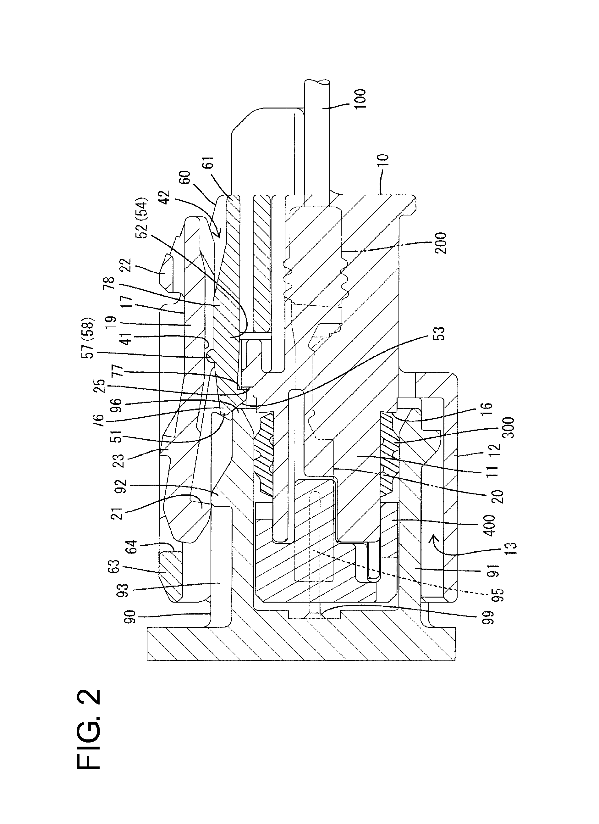
[0027]One embodiment of the present invention is described with reference to FIGS. 1 to 13. This embodiment includes first and second housings 10, 90 connectable to each other, a slider 60 to be assembled with the first housing 10, spring members 80 to be assembled with the slider 60, first terminal fittings 20 to be mounted into the first housing 10 and second terminal fittings 99 to be mounted into the second housing 90. Note that, in the following description, connection surface sides of the first and second housings 10, 90 are referred to as front sides concerning a front-back direction and a vertical direction is based on FIG. 1.

[0028]The second housing 90 is made of synthetic resin and includes, as shown in FIG. 1, a tubular receptacle 91. Tabs 95 of the second terminal fittings 99 are arranged to project into the receptacle 91. A lock portion 92 is provided to project on the upper surface of the upper wall of the receptacle 91. Further, as shown in FIG. 6, a pair of guide pro...


PUM


Abstract

In the process of connecting first and second housings (10, 90), a slider (60) is kept at an advanced position by locking a resilient stopper (76) and a stopper receiving portion (25), and springs (80) accumulate spring forces. The resilient stopper (76) and the stopper receiving portion (25) are released as the housings (10, 90) are connected and the slider (60) is moved to a retracted position while being biased by the springs (80). The resilient stopper (76) projects from a base end (52) to a tip (51) and has a first support (54) at the base end (52) to function as a support of deflection when starting deflection in the process of connecting the first and second housings (10, 90) and a second support (58) closer to the tip (51) than the base end (52) to function as a support of deflection following the first support (54).

Description

BACKGROUND[0001]1. Field of the Invention[0002]The present invention relates to a connector.[0003]2. Description of the Related Art[0004]A connector disclosed in Japanese Unexamined Patent Publication No. 2000-77138 includes first and second housings connectable to each other, a slider assembled with the first housing movably between an advanced position and a retracted position, and a coil spring interposed between the slider and the first housing. The second housing includes a releasing portion (called a “front end edge of a male housing” in Japanese Unexamined Patent Publication No. 2000-77138). Further, the first housing includes a stopper receiving portion (called a “hooking portion” in Japanese Unexamined Patent Publication No. 2000-77138) and the slider includes a resilient stopper (called a “holding arm” in Japanese Unexamined Patent Publication No. 2000-77138) capable of resiliently locking the stopper receiving portion.[0005]In the process of connecting the first and secon...

Claims


Application Information

Patent Timeline
IPC IPC(8): H01R13/502
CPCH01R13/502H01R13/641H01R13/4368
Inventor TANIKAWA, NAOTAKA
Owner SUMITOMO WIRING SYST LTD
Features
  • Generate Ideas
  • Intellectual Property
  • Life Sciences
  • Materials
  • Tech Scout
  • Unparalleled Data Quality
  • Higher Quality Content
  • 60% Fewer Hallucinations
Learn More